Backlight module

A backlight module and fluorescent technology, applied in optics, optical elements, diffraction gratings, etc., can solve the problems of poor light uniformity and low light source utilization of backlight modules, and achieve consistent brightness, high light uniformity, and brightness high effect

Inactive Publication Date: 2005-04-20
HONG FU JIN PRECISION IND (SHENZHEN) CO LTD +1
View PDF1 Cites 22 Cited by
  • Summary
  • Abstract
  • Description
  • Claims
  • Application Information

AI Technical Summary

Problems solved by technology

[0006] In order to solve the problems of low light source utilization rate and poor light uniformity of the backligh

Method used


Image

  • Backlight module
  • Backlight module
  • Backlight module

Examples


Embodiment Construction

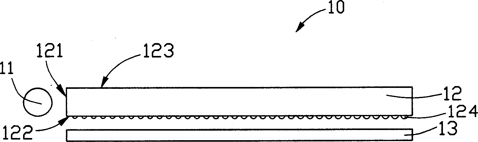
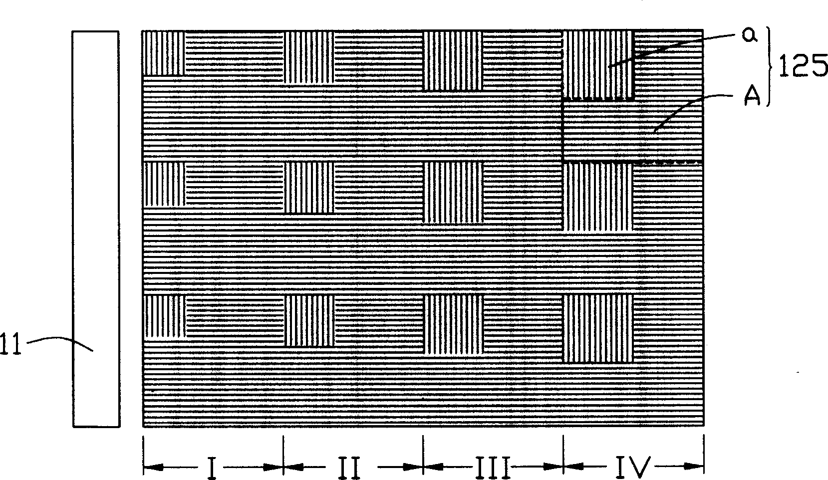
[0015] see figure 2 and image 3 According to the first embodiment of the present invention, the backlight module 10 includes a line light source 11 , a light guide plate 12 and a reflective sheet 13 . Wherein, the line light source 11 is a cold cathode fluorescent lamp (Cold Cathode Fluorescent Lamp, CCFL), the light guide plate 12 includes a light-emitting surface 123 provided with a plurality of transmissive grating units 125, and a set opposite to the light-emitting surface 123, Furthermore, it has a bottom surface 122 with a plurality of dots 124 and a fluorescent coating (not shown in the figure), and a light incident surface 121 connected with the light exit surface 123 and the bottom surface 122 . The line light source 11 is disposed adjacent to the light incident surface 121 of the light guide plate 12 , and the reflection sheet 13 is disposed opposite to the bottom surface 122 of the light guide plate 12 .

[0016] The light guide plate 12 is flat and made of tran...


PUM


Abstract

This invention relates to a back light module set including a light source and a light guiding board comprising an exit surface, a base surface and at least an entrance surface, among which, the exit surface is set opposite to the base, said entrance surface is connected with said exit and the base surface, multiple transmission diffraction grating units are set on the exit surface, each one includes two zones arrayed vertically, the first zone is arrayed vertical to the direction of the nearest emit point connected with this place, the second zone grating array direction is vertical to that of the first zone.

Description

【Technical field】 [0001] The invention relates to a backlight module, in particular to a backlight module using a light guide plate with a grating structure. 【Background technique】 [0002] The backlight module in the prior art liquid crystal display includes a light source and a light guide plate. The light source is arranged relative to the light incident surface of the light guide plate. The light guide plate guides the transmission direction of the light beam emitted from the light source, and converts the line light source or point light source into a surface light source to emit. A plurality of dots are distributed on the bottom surface of the light guide plate to scatter the light beam transmitted inside the light guide plate, so as to improve the uniformity of the light beam emitted from the light guide plate. In order to further improve the light uniformity of the light guide plate, recently, the diffraction grating technology is used in the light guide plate to imp...

Claims


Application Information

Patent Timeline
IPC IPC(8): G02B1/10G02B5/02G02B5/18G02F1/13357
Inventor 陈杰良吕昌岳余泰成
Owner HONG FU JIN PRECISION IND (SHENZHEN) CO LTD
Why Eureka
Try Eureka