
Linear compression latch

A straight-line, latching technology, used in building locks, carpet fastening devices, mechanical equipment, etc., can solve problems such as reducing the degree of isolation between the closed body and the environment, and achieve the effect of easy sealing, simple assembly and installation

Inactive Publication Date: 2005-04-20
SOUTHCO
View PDF0 Cites 0 Cited by
  • Summary
  • Abstract
  • Description
  • Claims
  • Application Information

AI Technical Summary

Problems solved by technology

Therefore, in this type of application, it is not desirable to have a locking device and the lock itself that allow the internal and external communication channels of the closure to reduce the degree of isolation between the closure and the environment.

Method used


Image

  • Linear compression latch
  • Linear compression latch
  • Linear compression latch

Examples


Embodiment Construction

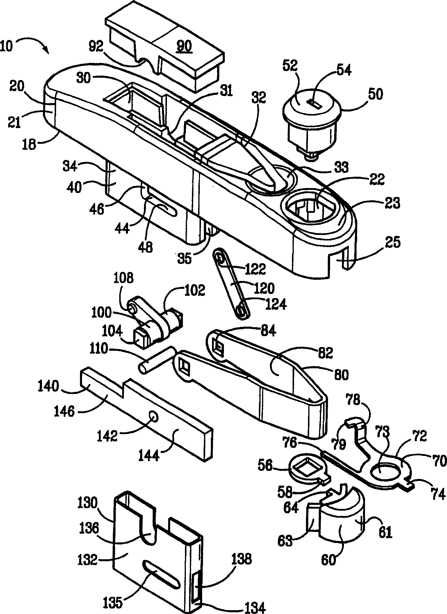
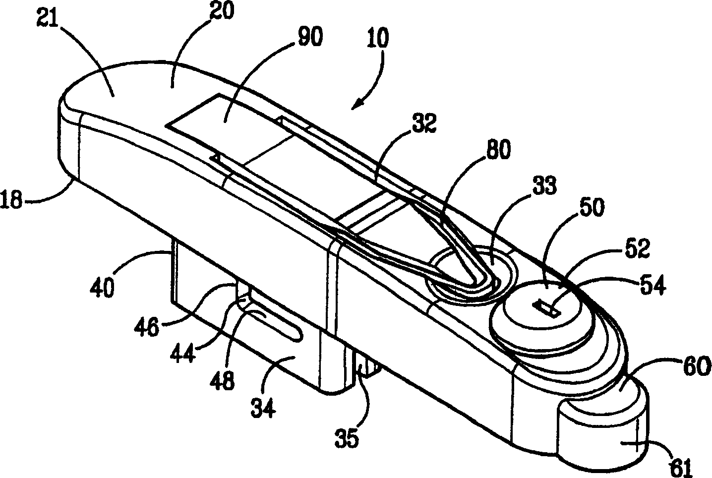
[0038] The present invention provides a simple straight line squeeze latch that can be easily and reliably installed on the outside of a door or panel. The straight line squeeze latch of the present invention sets steady preset compression. At the same time, only a small part of the latch mechanism protrudes inside the closure body, making the latch easy to seal against the environment. The linear extrusion latch of the present invention is simple to manufacture, assemble and install, and preferably can be assembled from less than a dozen parts.

[0039] According to the drawings, in which the same parts in the various views have the same references, figure 1 Shown is an exploded perspective view of a linear squeeze latch 10 in accordance with the present invention.

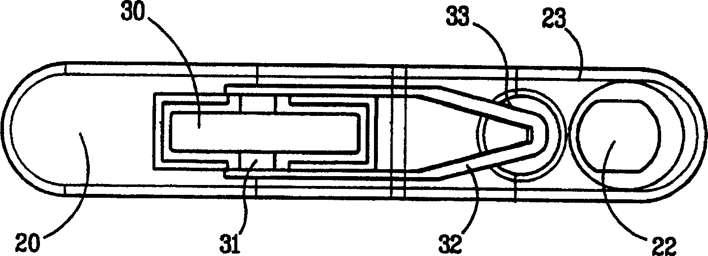
[0040] The linear squeeze latch 10 includes an elongated housing 20 for mounting on the outside of a door or panel 210 of a cabinet or enclosure 200 having a frame 220 ( Figure 14 ). The housing 20 includes...


PUM


Abstract

A straight squeeze latch including a lever hinged to a latch bar. When the latch is opened, the latch bar begins to be forced to move vertically with the bracket. When the intermediate position is reached, the latch bar is forced to move horizontally in the bracket.

Description

technical field [0001] This invention relates to squeeze latches for doors or panels. Background technique [0002] It is known to install squeeze latches on doors or panels. Squeeze latches are used in practice to simultaneously lock a door or panel to the frame in which the squeeze latch is mounted and to seal the edge of the panel to the frame when closed. For example, a squeeze latch may be used to compress the opening of a mounting panel provided with a gasket to provide a seal. [0003] Examples of squeeze latches are given by Southco Brochure 2000 (Southco, Inc., PA) pp. 23-69. [0004] The fixed squeeze latch provides the desired preset amount of squeeze, allowing the adjustable squeeze latch some flexibility in the amount of squeeze set. [0005] Squeeze latches typically include a latch bar that engages the frame on the inside of the closure to lock the closure's panels. Since the squeeze latch must be operated from the outside of the closure, a mechanism must...

Claims


Application Information

Patent Timeline
Patent Type & Authority Applications(China)
IPC IPC(8): E05B17/00E05C5/00
CPCE05B17/0025E05C5/00Y10S292/31Y10T292/102Y10T292/0876
Inventor T·维尔斯C·R·斯卡利
Owner SOUTHCO
Learn More