
Integrated electronic RF shielding apparatus for an MRI magnet

一种整体式、磁体的技术,应用在测量装置、磁场/电场屏蔽、应用等方向,能够解决地板空间昂贵、增加MRI系统成本等问题,达到维护成本低、成本低、防止图像伪影的效果

Inactive Publication Date: 2005-05-04
GE MEDICAL SYST GLOBAL TECH CO LLC
View PDF0 Cites 3 Cited by
  • Summary
  • Abstract
  • Description
  • Claims
  • Application Information

AI Technical Summary

Problems solved by technology

Floor space in inspection facilities (eg, hospitals) is expensive and only limited space is available
Also, additional work to be done by the MRI system manufacturer to separate the electronic components from the magnet structure also adds to the cost of the MRI system

Method used


Image

  • Integrated electronic RF shielding apparatus for an MRI magnet
  • Integrated electronic RF shielding apparatus for an MRI magnet
  • Integrated electronic RF shielding apparatus for an MRI magnet

Examples


Embodiment Construction

[0016] Although the present invention describes an arrangement for radio frequency shielding of a magnetic resonance imaging (MRI) magnet structure with proximal, integrally connected MRI system support electronics components therebetween, the following arrangements may be adapted for various purposes, and Applications without limitation are MRI systems, computed tomography systems, x-ray imaging systems, radiation therapy systems and other applications known in the art that require separation of the electronic components of the system from the magnetic or magnetic field generating structures.

[0017] In the following description, various operating parameters and elements are described in a constructed embodiment. These specific parameters and elements are included as examples and not meant to be limiting.

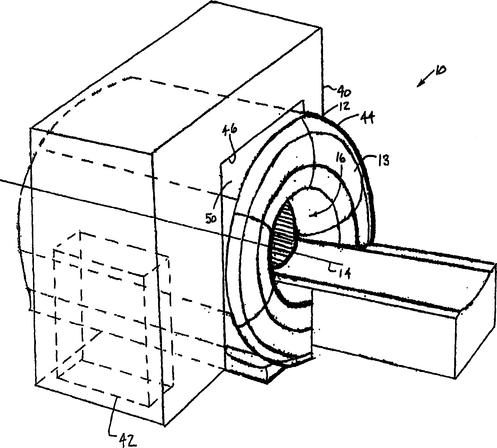
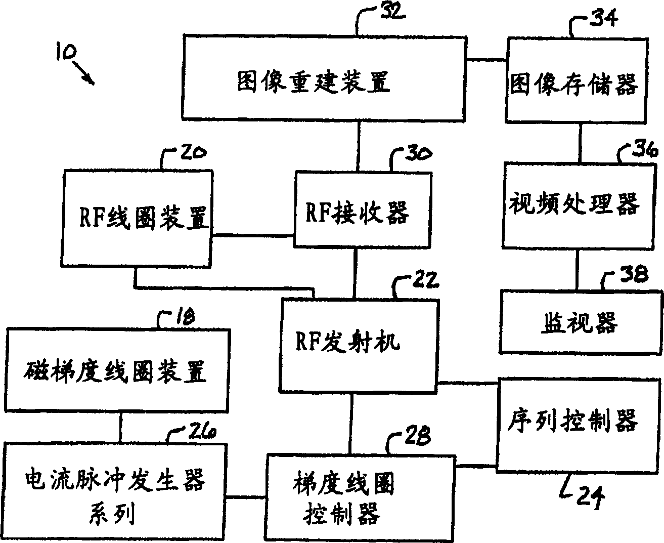
[0018] now refer to figure 1 and 2 , shows a perspective view of an MRI system 10 including an integrated electronics housing and a magnet structure 12, and a block dia...


PUM


Abstract

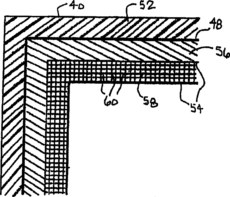
An integrated electronic system housing and magnet structure (12) for an imaging system (10) includes a housing (40) and a radio frequency shield (46). The housing (40) is coupled to the magnet structure (13) and contains imaging system support electronics (42). The radio frequency shield (46) is coupled to the housing (40) and prevents radio frequency interference of a radio frequency receiver coil (30) from the imaging system support electronics (42).

Description

technical field [0001] The present invention relates generally to magnetic resonance imaging (MRI) systems and assemblies. More particularly, the present invention relates to radio frequency shielding of MRI magnet structures with MRI system support electronics proximally and integrally connected therebetween. Background technique [0002] Current magnetic resonance imaging (MRI) systems include superconducting magnet structures that generate a temporarily constant primary magnetic field. A superconducting magnet is used in conjunction with a magnetic gradient coil arrangement that is pulsed in sequence to produce a controlled sequence of gradients within a static magnetic field during an MRI data collection sequence. The controlled sequence gradient runs through the entirety of the patient imaging volume (patient bore) to which one or more MRI radio frequency (RF) coils or antennas are connected. The RF coil is located between the magnetic gradient coil arrangement and th...

Claims


Application Information

Patent Timeline
Patent Type & Authority Applications(China)
IPC IPC(8): A61B5/055G01R33/422
CPCG01R33/422G01R33/28G01R33/42
Inventor T·J·哈文斯
Owner GE MEDICAL SYST GLOBAL TECH CO LLC
Learn More