
Automobile central brake method and apparatus

A braking method, automobile technology, applied in the direction of brakes, etc., can solve the problems of increased manufacturing cost and maintenance cost of the braking system, the functions of load-bearing and driving can not be used continuously, and it is difficult to realize, etc., to achieve good directional stability and braking. The effect of simple hoof structure and low cost

Inactive Publication Date: 2005-05-04
李战
View PDF0 Cites 0 Cited by
  • Summary
  • Abstract
  • Description
  • Claims
  • Application Information

AI Technical Summary

Problems solved by technology

[0005] In order to minimize the inconsistency of the braking force of the brakes on both sides, the braking system of the existing car is very complicated, and the reliability of the device is guaranteed with high manufacturing precision and assembly precision, which makes the manufacturing cost and maintenance of the car braking system greatly increased cost
[0006] The tires in existing automobiles not only undertake the functions of load-bearing and driving, but also undertake the function of braking due to sliding friction with the ground. Since the tires are scrapped due to the wear of the tread, the functions of load-bearing and driving cannot continue to be used.
Difficult to achieve equal life design, waste a lot

Method used


Image

  • Automobile central brake method and apparatus
  • Automobile central brake method and apparatus

Examples


Embodiment Construction

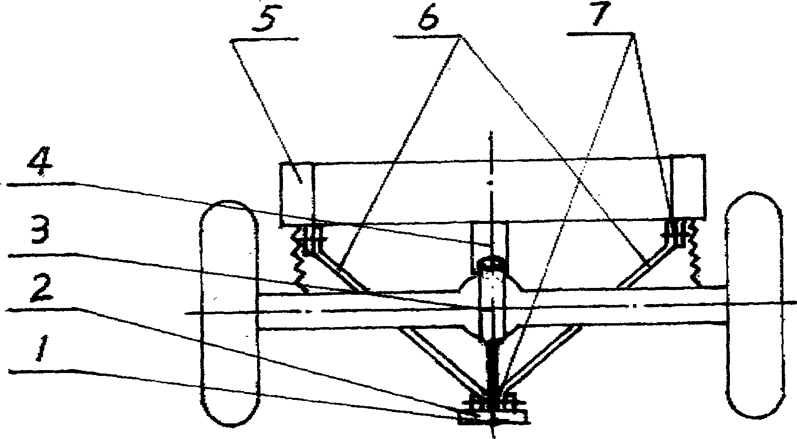
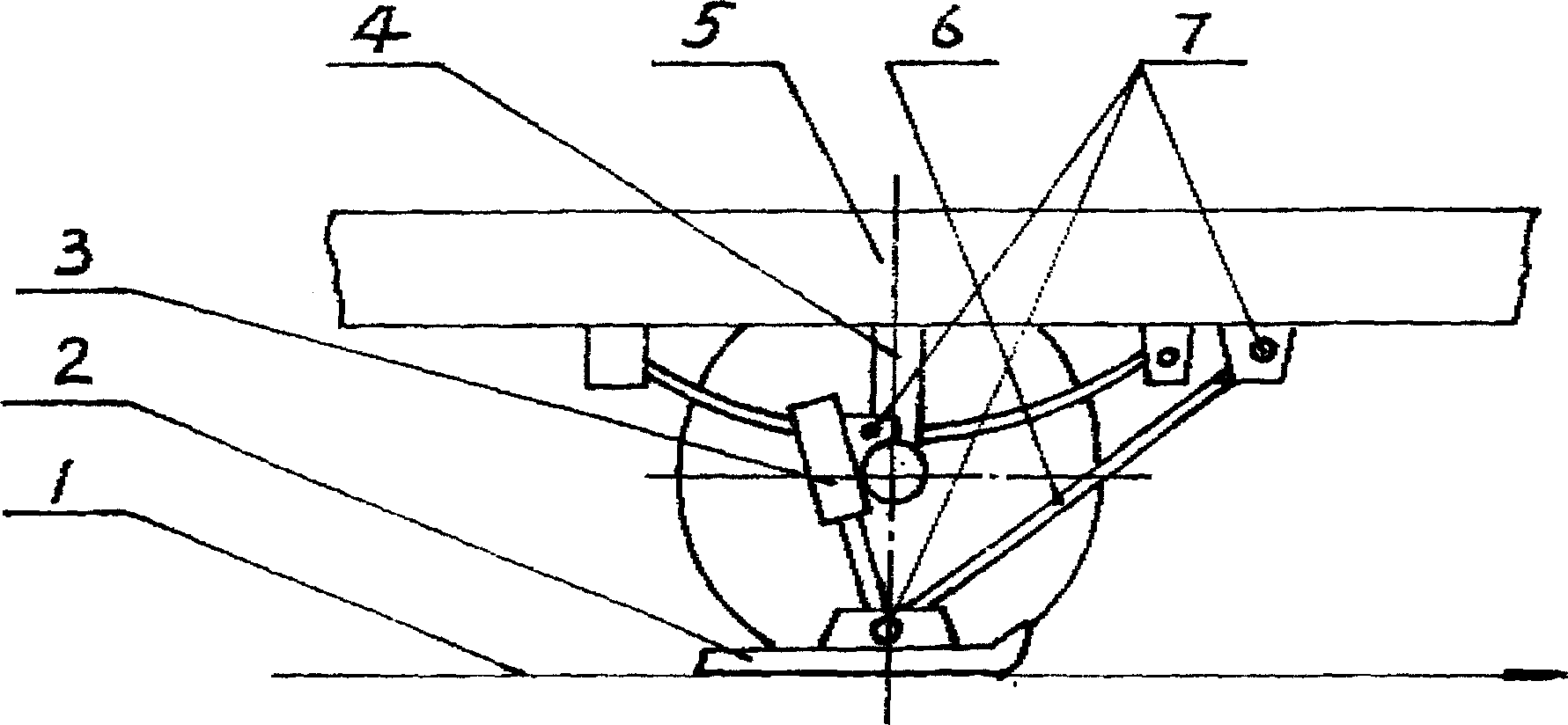
[0023] The present invention realizes like this for the braking of automobile: brake shoe 2 is connected on connecting rod 6 and pressure cylinder 3, and is positioned at wheel plane, and connecting rod 6 and pressure cylinder 3 are suspended below chassis 5 by hinge 7, The load-sensing pressure-limiting valve 4 is installed between the front and rear axles and the chassis 5, and connects the pressure cylinder 3 and the accumulator through a hose.

[0024] When braking, the driver activates the control system to activate the pressure cylinder 3, lowers the brake shoe 2 to contact the ground at the X-axis 1, and at the same time, depresses the clutch. During the whole braking process, the wheels are in a driven state and do not participate in the braking. . The descending height of the brake shoe 2 is controlled by the load-sensing pressure-limiting valve 4, so that the brake shoe 2 exerts an appropriate pressure on the ground when the vehicle has different loads, so as to keep...


PUM


Abstract

The present invention relates to a central brake method for automobile and its device. Said central brake method is characterized by that said brake point is positioned in one point or two points on the automobile X-axis (intersecting line of wheel surface-surface divided from middle of tire which is perpendicular to the wheel rotation axis-and ground surface. The brake shoe is suspended under the chassis and positioned in the wheel plane. When the automobile is braked, the brake shoe can be downward fallen into the ground surface X-axis, so that the wheel is in driven state, the loading sensing pressure limiting valve and pressure cylinder can be used for controlling the height of brake shoe so as to retain automobile balance. Said invention can raise brake effect of automobile and can prolong the life of tire.

Description

technical field [0001] The invention relates to the field of automobile braking. Background technique [0002] Existing automobiles utilize the sliding friction between the wheels and the ground to generate ground braking force to achieve the purpose of braking and parking. The wheels are located on both sides of the car body, that is, their braking points are located on both sides of the car's X-axis (the wheel plane—the tire middivision plane perpendicular to the wheel rotation axis—the intersection line with the ground), which is two-line four-point braking. Way. The left two tires are on the left brake line and the right two tires are on the right brake line. There is a certain distance between the two brake lines, that is, the wheelbase. The inconsistency of the braking force of the brakes on both sides of the car and the inconsistency of the road surface on both sides make the ground braking force on both sides of the car unequal. [0003] When the road braking for...

Claims


Application Information

Patent Timeline
Patent Type & Authority Applications(China)
IPC IPC(8): B60T8/00
Inventor 李战
Owner 李战
Learn More