
Power supply device and its designing method

A technology of a power supply and a design method, which can be applied to electrical components, output power conversion devices, etc., and can solve problems such as difficulty in implementation

Inactive Publication Date: 2005-05-04
ARIMA COMP
View PDF0 Cites 4 Cited by
  • Summary
  • Abstract
  • Description
  • Claims
  • Application Information

AI Technical Summary

Problems solved by technology

However, the disadvantage of this solution is that it is difficult to implement

Method used


Image

  • Power supply device and its designing method
  • Power supply device and its designing method
  • Power supply device and its designing method

Examples


no. 1 example

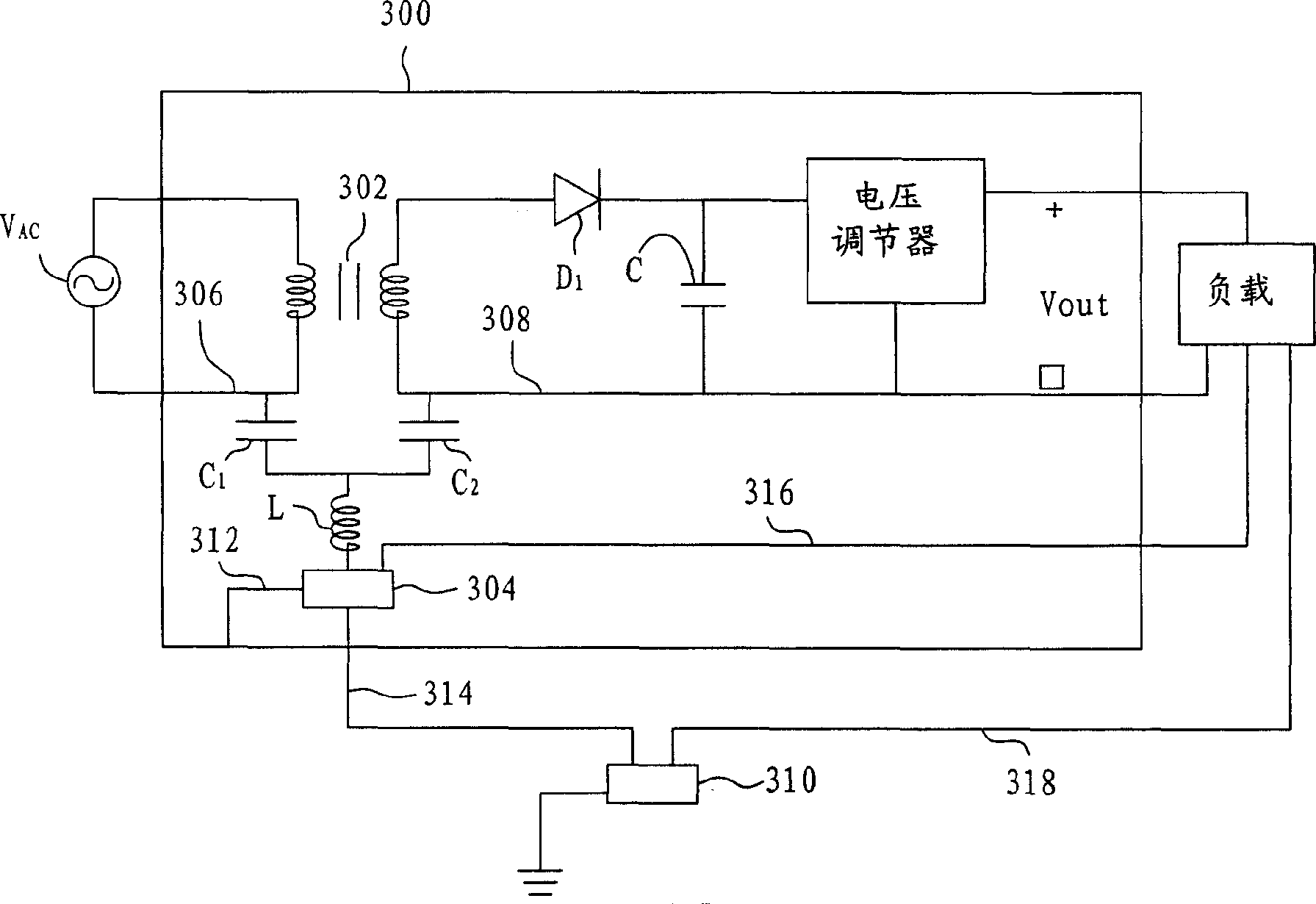
[0022] An embodiment of the present invention is described here. The suppression of signal interference can be achieved through noise control on the power supply or power adapter. Consider a typical power supply 300 in an electronic system, shown in image 3 . The power supply 300 includes a transformer 302, the first side of the transformer 302 is connected to an external AC input voltage source V AC A first-side circuit of the transformer 302 , a second-side circuit for generating the output voltage Vout of the power supply 300 on the second side of the transformer 302 , and a ground conductor 304 . The power supply 300 generates a DC voltage and a load current to supply the load block. The load block is a circuit or device, and the output voltage Vout is supplied to the load. Transformer 302 is used to increase or decrease the AC input voltage, and make the external AC voltage source V ACIsolated from the second side circuitry.

[0023] The second side circuit includes...

no. 2 example

[0029] Please refer to Figure 4 , another embodiment of the present invention is described here. The power supply 400 is also a typical power supply in an electronic system. The power supply 400 includes a transformer 402, the first side of the transformer 402 is connected to an external AC input voltage source V AC A first-side circuit of the transformer 402 , a second-side circuit of the second side of the transformer 402 that generates the output voltage Vout of the power supply 400 , and a ground conductor 404 . The power supply 400 generates a DC voltage and a load current to supply the load block. The load block is a circuit or device, and the output voltage Vout is supplied to the load. The ground conductor 404 is conductively connected to the non-current-carrying metal portion of the power supply 400 via a wire 412 and is connected to the load via a wire 416 for device grounding.

[0030] The ground conductor 404 is also connected to an external system ground 410 ...


PUM


Abstract

Power supplier is in use for restraining signal interference generated in electronic equipment caused by fluctuant earth current. The power supplier includes a transformer, a first side circuit, second side circuit, and grounded conductor. Through cascaded a capacitor and an inductor, the method connects the first side circuit and the second side circuit to grounded conductor. Added capacitor can filter out noise and interference in DC and low frequencies components as well as help to maintain representation of lowered electromagnetic interference. Added inductor is in use for getting rid of noise in high frequency and interference. Most part of noise and interference signal is not possible to pass through conduction route formed. The result of the grounded method is that interfere degree is reduced greatly.

Description

(1) Technical field [0001] This invention relates to the suppression of signal interference in electronic equipment, and in particular to the use of new grounding techniques in power supplies or adapters to suppress varying ground currents (ground current) Signal interference generated in electronic equipment. (2) Background technology [0002] Grounding is an important part of computer, electrical and electronic systems. According to the Institute of Electrical and Electronics Engineers (IEEE), grounding is defined as a conducting connection. A conductive connection, whether intentional or accidental, by which a circuit or electronic device is connected to the earth or to a relatively large conductive body. The object that replaces the surface. Grounding is used to establish and maintain the potential of the earth's surface (or this conductive object) on the conductor connected to the earth's surface (or this conductive object), or a potential similar to it, and to condu...

Claims


Application Information

Patent Timeline
IPC IPC(8): H02M1/12
Inventor 张崇兴
Owner ARIMA COMP
Learn More