
Eureka
For R&D, Eureka makes reading and utilizing patents & technical documents easy.
Eureka AIR
Designed for self-driven R&D workflows. Generate viable solutions, solve complex R&D challenges, empower your innovation with AI.

Eureka Materials
Designed for material experts only. Revolutionize your material R&D, from search, analyze, to developing new materials.

TechResearch
Generate reliable direction feasibility study reports for your R&D in just a few steps.

TechSeek
Discover and master advanced knowledge NOW. Basics, ideas, possibilities, all at once.

TechMind
As an expert in R&D Theories, TechMind can generates customized viable solutions instantly.

TechRisk
Analyze your overall solution with one click, know your potential R&D risks in advance.

TechMonitor
Get weekly tech updates, stay abreast of the latest tech innovations and key insights.
Lighting device for discharge lamp
A discharge lamp and lighting technology, which is applied to the layout of electric lamp circuits, lighting devices, electric light sources, etc., and can solve the problems of large and expensive switching units
- Summary
- Abstract
- Description
- Claims
- Application Information
AI Technical Summary
Problems solved by technology
Method used
Image

Examples
Embodiment Construction
[0019] Implementation form 1
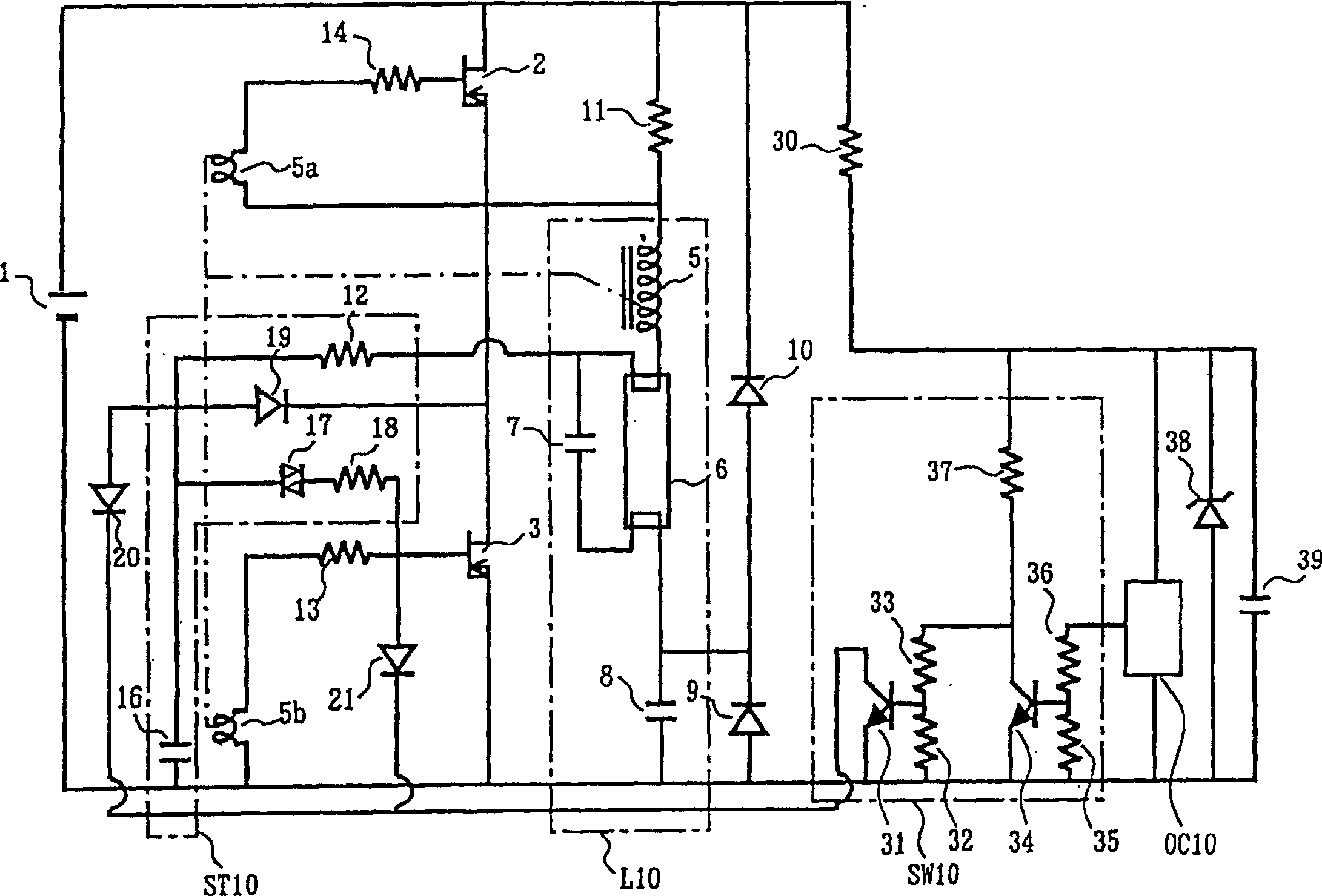
[0020] figure 1 It is a circuit diagram showing a discharge lamp lighting device according to an embodiment of the present invention. In the drawing, a DC power supply 1 is obtained by rectifying a commercial power supply with, for example, a diode bridge and smoothing it with an electrolytic capacitor. A series circuit of MOSFETs 2 and 3 as switching elements is connected to the DC power supply 1 to constitute an inverter circuit. Resistor 11 is connected in parallel with MOSFET2. The choke coil 5 , the discharge lamp 6 , and the coupling capacitor 8 are connected in series, and these series circuits are connected in parallel with the switching element 3 . A capacitor 7 is connected in parallel to the discharge lamp 6 . The anode of the diode 9 is connected to the negative pole of the DC power supply 1 , and the cathode is connected to the connection point of the coupling capacitor 8 and the discharge lamp 6 . The anode of diode 10 is conn...
PUM
 Abstract
Description
Claims
Application Information
 - R&D Engineer
- R&D Manager
- IP Professional
- Industry Leading Data Capabilities
- Powerful AI technology
- Patent DNA Extraction
Browse by: Latest US Patents, China's latest patents, Technical Efficacy Thesaurus, Application Domain, Technology Topic, Popular Technical Reports.
© 2024 PatSnap. All rights reserved.Legal|Privacy policy|Modern Slavery Act Transparency Statement|Sitemap|About US| Contact US: help@patsnap.com