
Fuel cell system

A fuel cell system and fuel cell technology, applied in fuel cells, fuel cell additives, fuel cell heat exchange, etc., can solve problems such as increased cost and system complexity.

Inactive Publication Date: 2005-05-18
BALLARD POWER SYSTEMS
View PDF1 Cites 19 Cited by
  • Summary
  • Abstract
  • Description
  • Claims
  • Application Information

AI Technical Summary

Problems solved by technology

This approach typically requires a separate battery charging source to keep the battery charged, adding expense and system complexity

Method used


Image

  • Fuel cell system
  • Fuel cell system
  • Fuel cell system

Examples


Embodiment

[0119] Figure 13-15 Three different electrical configurations of the fuel cell system 10 of the two-dimensional array 568 of FIG. is 4kW. especially, Figure 13 An illustration showing four fuel cell systems 10(1,1)-10(4,1) employing the first column of a two-dimensional array 568 electrically connected in series to provide 4 kW of power at 96 volts and 40 amps . Figure 14 shows a schematic of the first row of four fuel cell systems 10(1,1)-10(4,1) of a two-dimensional array 568 electrically connected in parallel to provide 4kW of power at 24 volts and 160 amps example. Figure 15 shows a schematic example of four fuel cell systems 10(1,1), 10(1,2), 10(2,1), 10(2,2) using a two-dimensional array 568, where two pairs of series-connected Fuel cell systems 10(1,1), 10(2,1) and 10(1,2)10(2,2) are connected in parallel to generate 4kW of power at 48 volts and 80 amps. Those skilled in the art will recognize that other combinations and permutations of fuel cell system 10 elec...


PUM


Abstract

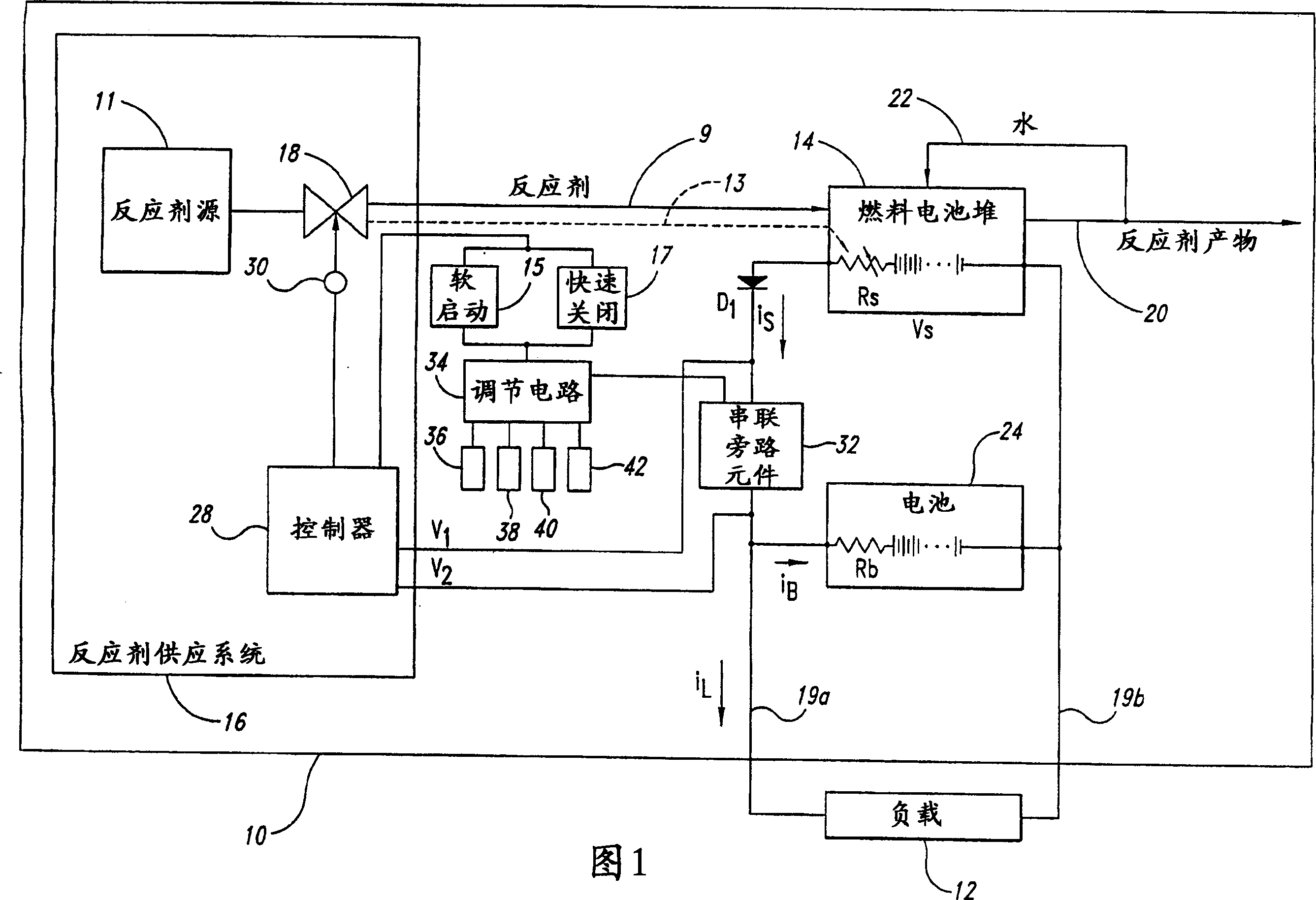
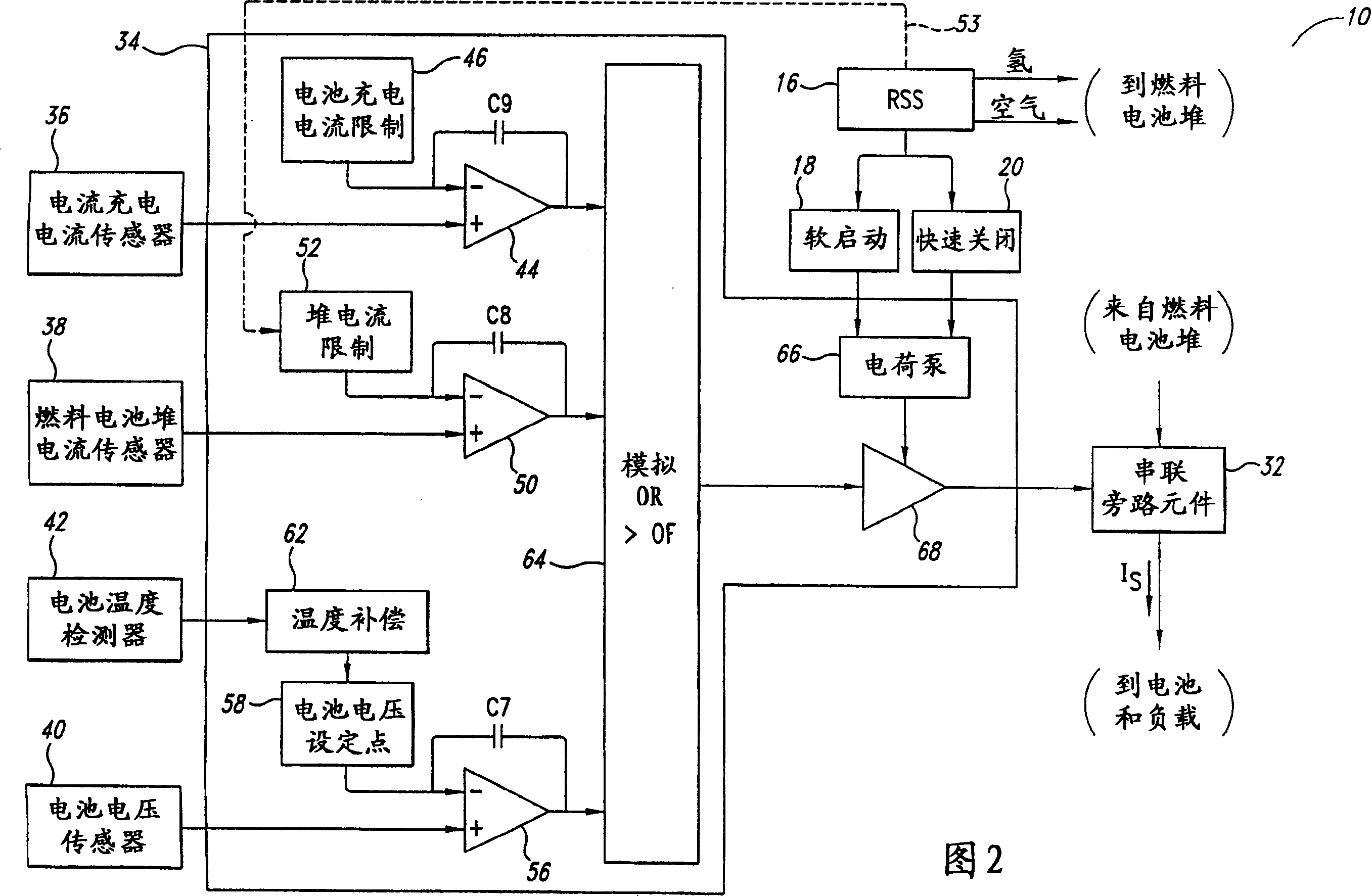
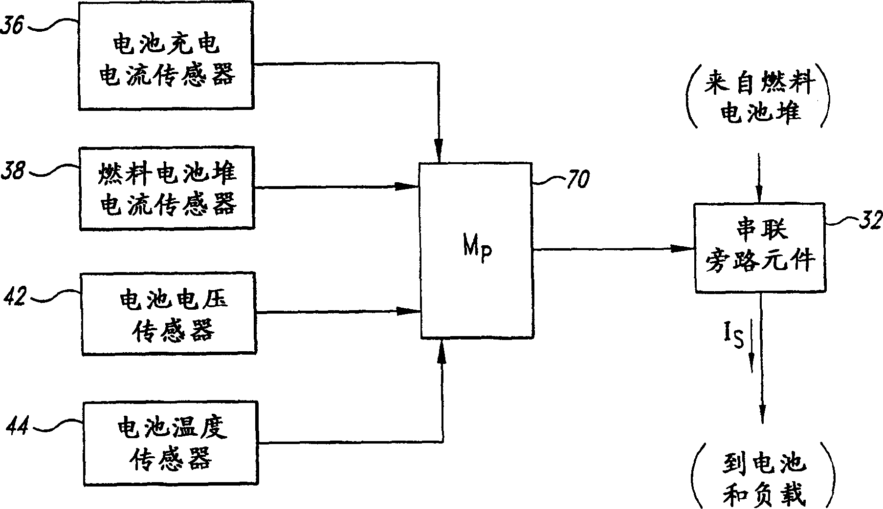
A fuel cell system having a battery employs a first stage that regulates current through a series pass element in response to a greater of a battery charging current error, a battery voltage error and a stack current error. The fuel cell system employs a second stage that controls a partial pressure of a reactant flow to the fuel cell stack based on a deviation of voltage across the series pass element, or based on a battery condition. The fuel cell system may employ either, or both, of the stages. Individual fuel cell systems can be combined in series and / or parallel to produce a combined fuel cell system having a desired output voltage and current.

Description

technical field [0001] The present invention relates generally to fuel cell systems, and in particular to controlling the output voltage of the fuel cell system. Background technique [0002] Electrochemical fuel cells convert fuel and oxidant into electricity. Solid polymer electrochemical fuel cells typically employ a membrane electrode assembly ("MEA") comprising an ion exchange membrane or a solid polymer electrolyte disposed between two electrodes typically comprising a porous, electrically conductive sheet of material layer, such as carbon fiber paper or carbon cloth. The MEA contains a catalyst layer in the form of finely ground platinum at each membrane-electrode interface to induce the desired electrochemical reactions. In operation, the electrodes are electrically connected by an external circuit to conduct electrons between the electrodes. Typically, multiple MEAs are electrically connected in series to form a fuel cell stack with the desired power output. [...

Claims


Application Information

Patent Timeline
IPC IPC(8): H02J7/00H01M8/00H01M8/04H01M8/10H01M10/44H01M16/00H02J7/34
CPCH01M8/04007H01M8/04119H01M8/0432H01M8/04567H01M8/04589H01M8/04597H01M8/04753H01M8/04895H01M16/006H02J1/001H02J1/082H02J7/34H02J2300/30Y02E60/10Y02E60/50
Inventor 马丁·T.·皮尔逊
Owner BALLARD POWER SYSTEMS
Learn More