
Switching type power switching circuit and saturable transformer

A power conversion circuit, switching technology, applied in the direction of conversion equipment with intermediate conversion to AC, etc., can solve the problems of conduction loss, power conversion efficiency reduction, affecting power supply and transmission, etc.

Inactive Publication Date: 2005-06-01
GAOYIDA SCI & TECH SHENZHEN
View PDF0 Cites 0 Cited by
  • Summary
  • Abstract
  • Description
  • Claims
  • Application Information

AI Technical Summary

Problems solved by technology

[0007] Although the above-mentioned soft switching technology can reduce the switching loss generated by the switching switch due to zero-voltage switching, the oscillating circuit brings a large amount of tank current, which will be generated in the circuit Conduction loss, and the conduction loss will seriously affect the supply and transmission of power, reducing the conversion efficiency of the power supply

Method used


Image

  • Switching type power switching circuit and saturable transformer
  • Switching type power switching circuit and saturable transformer
  • Switching type power switching circuit and saturable transformer

Examples


Embodiment Construction

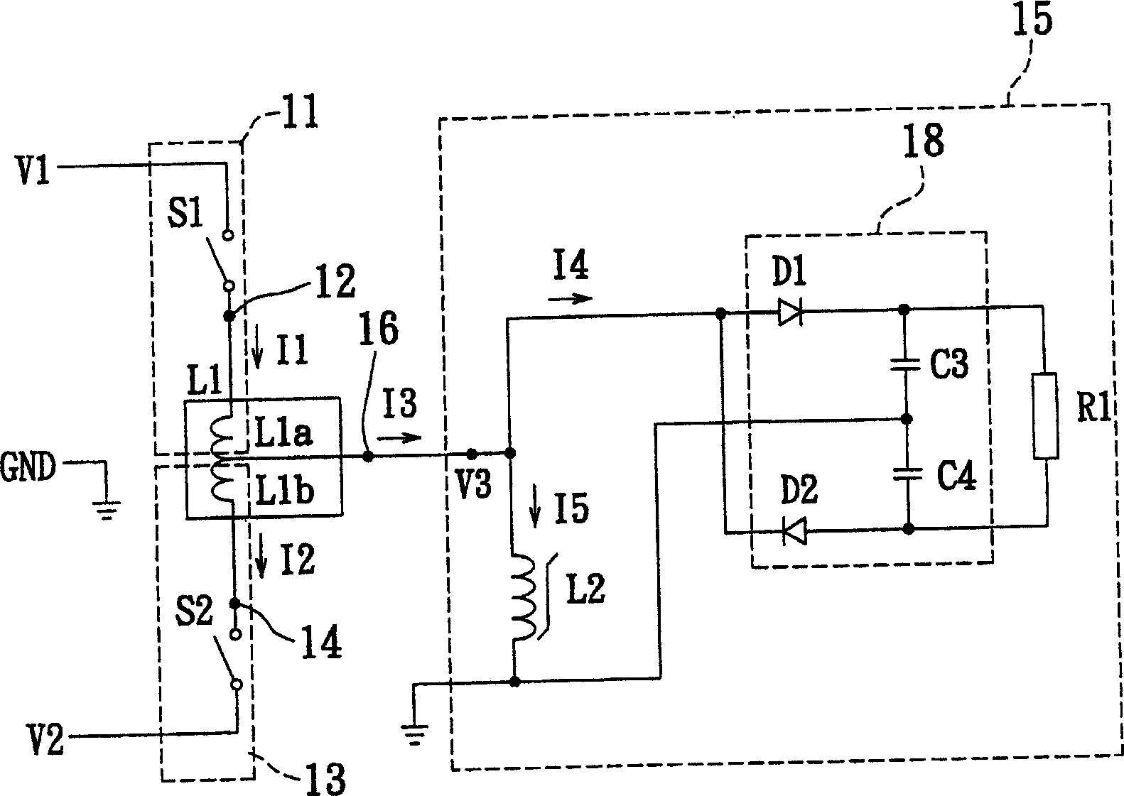
[0061] see figure 2, which is a switching power conversion circuit diagram of the first embodiment of the present invention. Wherein the first switchable inductance coil assembly 11 is composed of the first switch S1 connected in series with the first coil L1a, the second switchable inductance coil assembly 13 is composed of the second switch S2 connected in series with the second coil L1b, and the saturable load assembly 15, It consists of a load R1 via a rectifier circuit 18 and a saturable reactor L2, wherein the first coil L1a and the second coil L1b are magnetically coupled to form the main inductance coil L1, and the middle part of the main inductance coil L1 is provided with an intermediate terminal 16, so the middle The terminal 16 divides the main inductance coil L1 into the first coil L1a and the second coil L1b, the other terminal of the first coil L1a is the first terminal 12 of the main inductance coil L1, and the other terminal of the second coil L1b is the main...


PUM


Abstract

When the switched power source converting circuit is switched to supply power, the saturation effect of the saturable reactor makes the end potential of the switch before conducting become zero potential. The switched power source converting circuit includes one saturable load module comprising one load and one saturable reactor; one first switched inductor coil module connected to the load module and one first potential; and one second switched inductor coil module coupled magnetically to the first switched inductor coil module and connected to the first switched inductor coil module and one second potential. The first switched inductor coil module and the second switched inductor coil module are used in the power supply switching, and the saturation effect of the saturable reactor makes the reactor end potential drop and the switch end potential become zero. The present invention also provides one kind of magnetically saturated transformer.

Description

technical field [0001] The invention relates to a switching power conversion circuit and a transformer, in particular to a switching power conversion circuit and a saturable transformer whose crossover potential of the switch is zero potential when the power supply is switched through a switch. Background technique [0002] For high-efficiency switching power converters, zero-voltage switching is a very important part of the technology. Since switching power converters need to flow through the entire load current when switching, the switches will withstand high switching stress ( switching stress) and high switching loss proportional to the switching frequency. [0003] In addition, the di / dt (current change rate) and dv / dt (voltage change rate) caused by high-speed switching will cause serious electromagnetic interference (EMI). [0004] In order to reduce the volume and weight of the converter to increase its power density, its switching frequency must be increased, which...

Claims


Application Information

Patent Timeline
Patent Type & Authority Applications(China)
IPC IPC(8): H02M3/28
Inventor 张志雄
Owner GAOYIDA SCI & TECH SHENZHEN
Learn More