
Vortex compressor

A scroll compressor and volute technology, applied in the field of scroll compressors, can solve problems such as performance degradation, insufficient compression, and increased indicated power, and achieve the effects of improving efficiency, preventing the increase of indicated power, and preventing internal leakage

Inactive Publication Date: 2005-06-22
HITACHI JOHNSON CONTROLS AIR CONDITIONING INC
View PDF2 Cites 6 Cited by
  • Summary
  • Abstract
  • Description
  • Claims
  • Application Information

AI Technical Summary

Problems solved by technology

At this point, compression is only halfway to the necessary pressure, resulting in undercompression
[0012] In addition, under the condition of operating at a higher pressure ratio like when hydrocarbon refrigerant is used in the refrigeration cycle, there will be a problem of performance degradation caused by an increase in the indicated power due to insufficient compression.

Method used


Image

  • Vortex compressor
  • Vortex compressor
  • Vortex compressor

Examples


Embodiment Construction

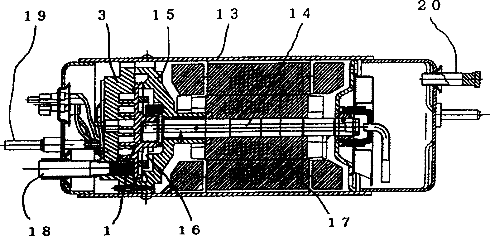
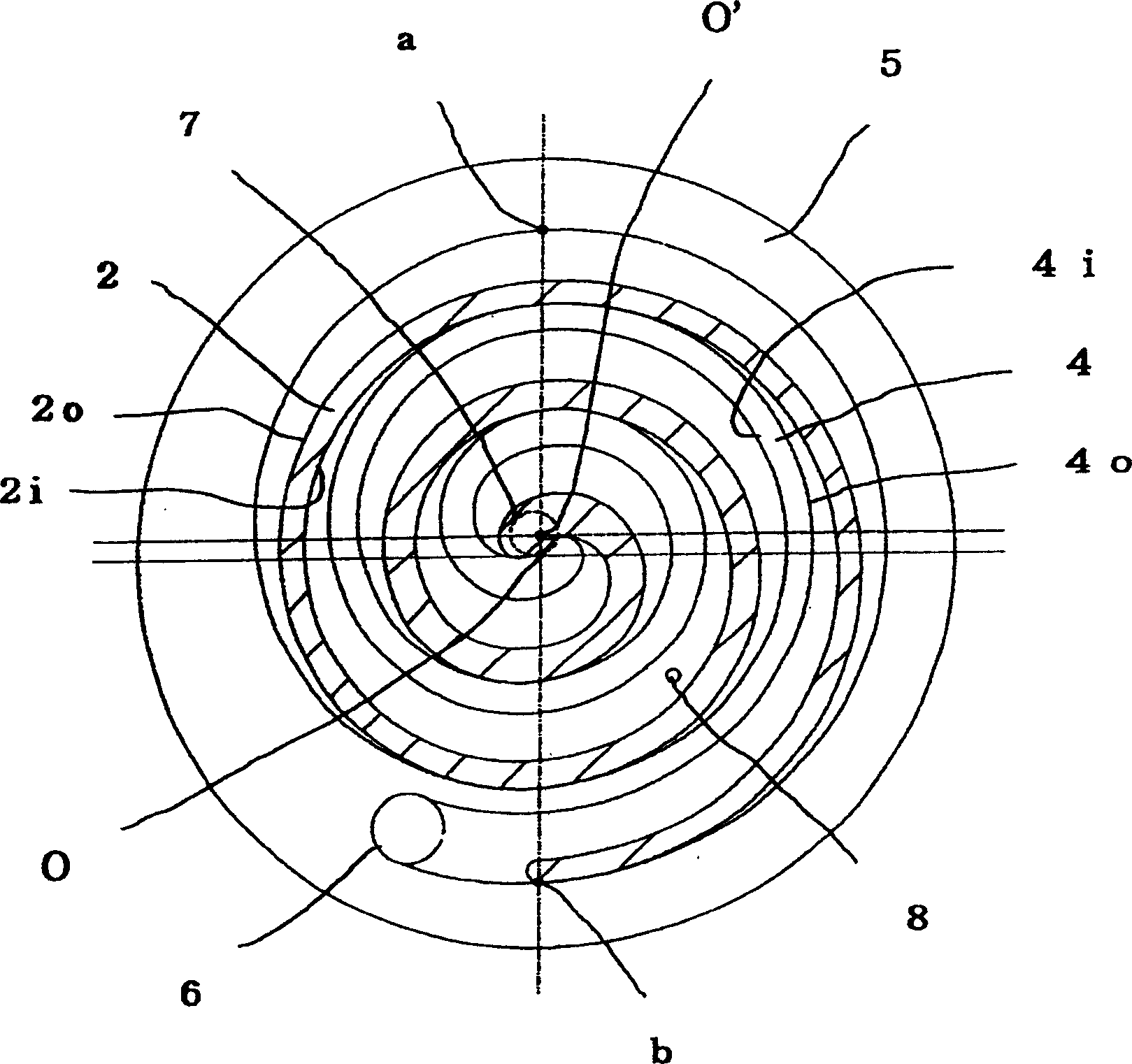
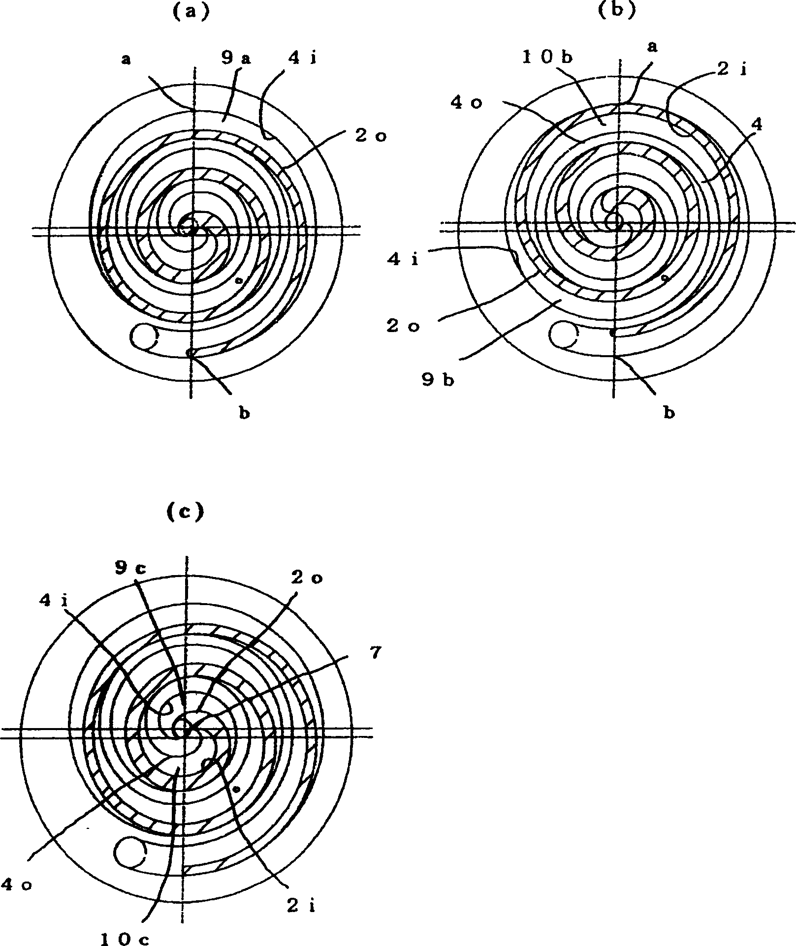
[0026] The following is based on Figure 1 to Figure 6 Examples of the present invention will be described.

[0027] figure 1 A longitudinal sectional view showing a scroll compressor according to an embodiment of the present invention. The scroll compressor 13 has a rotating scroll 1 and a fixed scroll 3, a crank shaft 14 that rotates the rotating scroll 1, a bracket 15 that supports the crank shaft 14, and an Oldham ring 16 that allows the orbiting motion of the rotating scroll 1 and prevents rotation. , the motor 17 that drives the crankshaft 14 . The helicoids of the two volutes 1 and 3 have a basic vortex curve which is a reference curve defining the helical shape as an algebraic helical curve. By making the deflection angle of the spiral body of the fixed scroll 3 approximately 180 degrees larger than the deflection angle of the orbiting scroll 1, the rotation end position of the fixed scroll 3 is extended beyond the same position as the rotation end position of the o...


PUM


Abstract

A scroll compressor, wherein in a rotating scroll and a fixed scroll having a spiral formed by using an algebraic spiral curve as a basic vortex curve, the inner wall surface of the fixed scroll spiral body is extended to a point beyond the outer wall surface of the rotating scroll spiral body Position, the center of the basic vortex curve and the center of the end plate are staggered, and the liquid jet inlet is arranged at a position where the closed space with a smaller design volume ratio is connected for a long time. As a result, the scroll compressor can increase the volume ratio while using the same outer diameter of the spiral body, and can be more efficient when operating at a high pressure ratio.

Description

technical field [0001] The present invention relates to a scroll compressor as a type of positive displacement fluid machine, and particularly relates to a scroll used for freezing and refrigeration using a working fluid such as R404A, R507A, R508B, R410A, hydrocarbon, carbon dioxide, ammonia, and other low-temperature refrigerants compressor. Background technique [0002] Since the pressure ratio reaches 4 to 20 in the refrigerating cycle of the refrigerating machine, in the conventional helix whose basic vortex curve is a circular involute, the volume change rate is constant. Therefore, in order to make the compression chamber formed by the helix The ratio of the volume at the end of suction to the volume at the beginning of discharge (hereinafter referred to as the design volume ratio) corresponds to the necessary pressure ratio, and there is no other means except to increase the spiral angle and increase the outer diameter of the spiral, so It is difficult to achieve an...

Claims


Application Information

Patent Timeline
Patent Type & Authority Applications(China)
IPC IPC(8): F04C29/00F04C18/02
Inventor 土屋直洋小山昌喜香曾我部弘胜
Owner HITACHI JOHNSON CONTROLS AIR CONDITIONING INC
Learn More