Cooling device for built-in-spindle type spindle motor of machine tool

A technology for spindle motors and cooling equipment, applied in electromechanical devices, electric components, cooling/ventilation devices, etc., can solve problems such as preventing high temperature, cooling efficiency degradation, and inability to cool rotors and stators

Active Publication Date: 2005-06-22
DN SOLUTIONS CO LTD
View PDF1 Cites 16 Cited by
  • Summary
  • Abstract
  • Description
  • Claims
  • Application Information

AI Technical Summary

Problems solved by technology

However, because the cooling equipment also adopts a structure that cannot cool the rotor and the stator, and the heat is mainly generated in the rotor and the stator, it is impossible to fundamentally prevent the generation of high temperature for the cooling equipment, and as a result, the heat generated in the rotor and the stator continues continuously. ground to the spindle, so there is a problem of degraded cooling efficiency

Method used


Image

  • Cooling device for built-in-spindle type spindle motor of machine tool
  • Cooling device for built-in-spindle type spindle motor of machine tool
  • Cooling device for built-in-spindle type spindle motor of machine tool

Examples


Embodiment Construction

[0021] Next, preferred embodiments of the cooling apparatus for an internal shaft type spindle motor according to the present invention will be described in detail with reference to the accompanying drawings. Parts that are the same as those of the conventional equipment described above will use the same reference numerals as in the prior art.

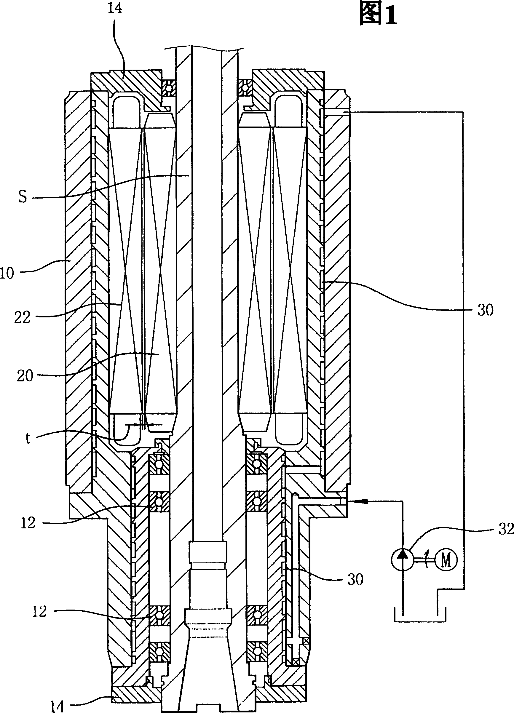
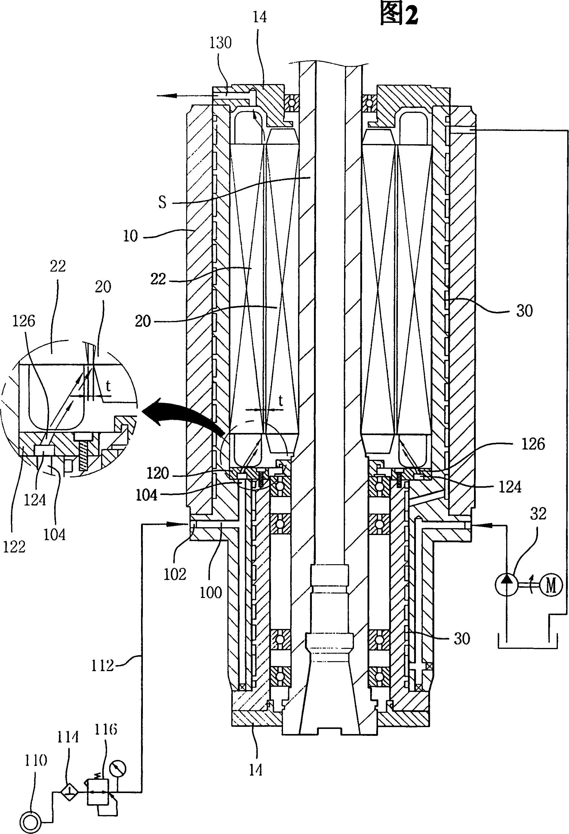
[0022] Before explaining the spindle motor cooling device of the present invention, the structure of the spindle motor will be briefly described with reference to FIG. 2 . As shown, the spindle motor includes a motor housing 10 . The motor housing 10 is provided to enclose the main shaft S. As shown in FIG. Opposite ends of the motor housing 10 are sealed with covers 14 .

[0023] In addition, the spindle motor includes a rotor 20 fixed around the rotor 20 and a stator 22 disposed around the rotor 20 with a gap formed between the rotor and the stator. The stator 22 is fixed to the inner circumferential surface of the motor housing 1...


PUM


Abstract

A cooling device for cooling a built-in shaft type spindle motor of a machine tool, wherein the spindle motor includes a motor casing enclosing the spindle, a rotor fixed around the spindle, and a stator fixed on the inner peripheral surface of the motor casing around the rotor, between the rotor and the stator forming a gap, wherein the cooling device includes: a cooling air supply device for supplying cooling air; a motor housing having a cooling air introduction passage for introducing cooling air supplied from the cooling air supply device to one side of the rotor and the stator; And a cooling air injection nozzle, which is detachably installed in the motor housing and has one or more nozzle openings that can inject cooling air into the gap between the rotor and the stator.

Description

technical field [0001] The present invention relates to a cooling device for a spindle motor for driving a machine tool spindle, and more particularly to a cooling device for a spindle motor with a built-in shaft in a machine tool, which can effectively cool the spindle motor. Background technique [0002] Machine tools such as numerically controlled lathes, machining centers, or the like have a spindle motor for rotating the spindle. Such spindle motors tend to be of the built-in type, in which the spindle motor is integrated with the spindle. The built-in spindle motor rotates the spindle without noise and vibration. [0003] As shown in FIG. 1 , such a built-in spindle motor includes a motor housing 10 . The motor housing is arranged to enclose the main shaft S. Here, a corresponding bearing 12 is provided between the motor housing 10 and the main shaft S to assist the rotation of the main shaft S. As shown in FIG. In addition, the opposite open side of the motor hous...

Claims


Application Information

Patent Timeline
Patent Type & Authority Applications(China)
IPC IPC(8): H02K5/20H02K7/00H02K9/00H02K9/04H02K9/08H02K9/10H02K9/12H02K9/19
CPCH02K5/203H02K5/20H02K5/207H02K9/08H02K2205/09
Inventor 金仁灿
Owner DN SOLUTIONS CO LTD
Why Eureka
Try Eureka