Perceptive bionic manipulator for clinical injured finger rehabilitation

A technology of manipulators and fingers, which is applied in the field of rehabilitation devices for traumatic fingers, can solve problems such as poor sensory function, lack of joint position, precise control of joint speed and rehabilitation force, force position information and rehabilitation effect cannot be established for effective evaluation, etc.

Inactive Publication Date: 2005-06-29
HARBIN INST OF TECH
View PDF0 Cites 8 Cited by
  • Summary
  • Abstract
  • Description
  • Claims
  • Application Information

AI Technical Summary

Problems solved by technology

There have been CPM machines applying this theory in foreign countries, but there are still great limitations, concentrated in: 1. The scope of application is small, and it is mostly used for single-joint rehabilitation of large joints such as knee joints, elbow joints or wrist joints; 2. The perception function is ...

Method used


Image

  • Perceptive bionic manipulator for clinical injured finger rehabilitation
  • Perceptive bionic manipulator for clinical injured finger rehabilitation
  • Perceptive bionic manipulator for clinical injured finger rehabilitation

Examples


specific Embodiment approach 1

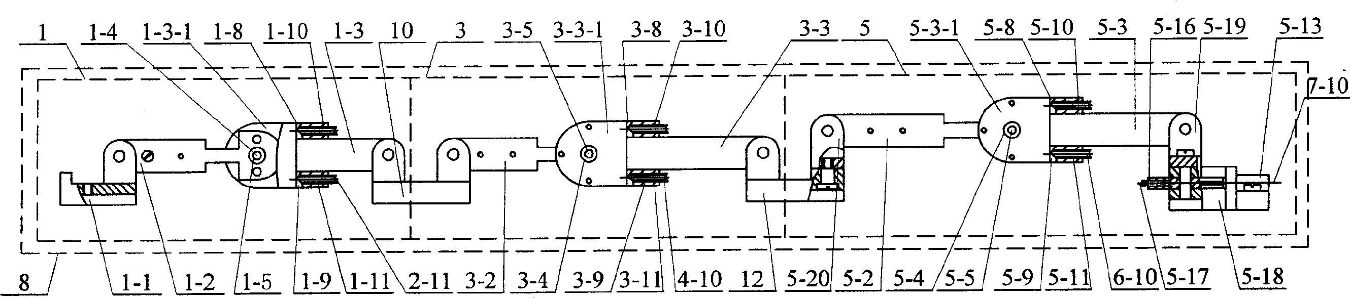
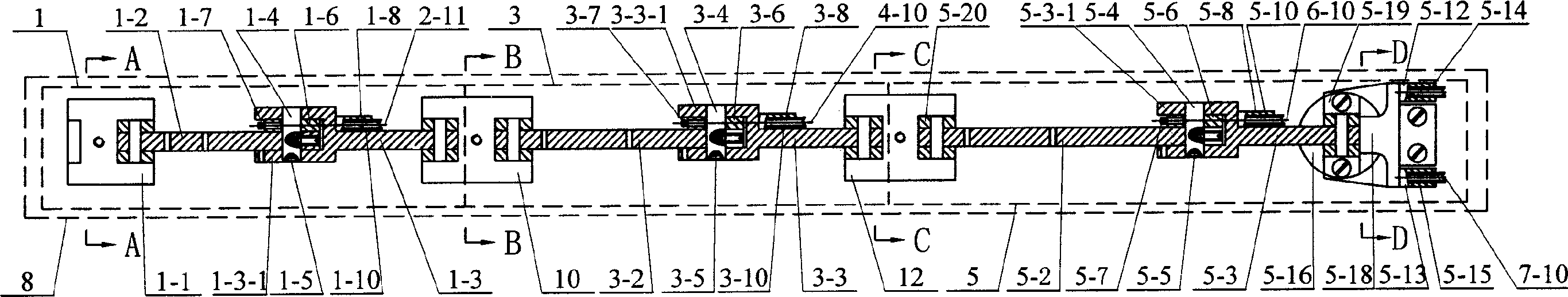
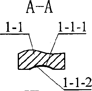
[0006] Specific implementation mode one: combine figure 1 , figure 2 ,image 3, Figure 4 Describe this embodiment, this embodiment is made up of the 3rd bionic finger module 1, frame assembly 11 and nail bionic muscle module 2; , the third connecting rod 1-3, the third shaft 1-4, the third magnetic steel 1-5, the third pulley 1-6, the third fixed column 1-7, the first cylinder 1-8, the second cylinder Tube 1-9, first spring 1-10, second spring 1-11, and second base 10; third base 1-1 is hinged to the left end of third torque sensor 1-2, and third torque sensor 1 -2 and the third pulley 1-6 are contained in the fork 1-3-1 of the third connecting rod 1-3 and are connected with the third connecting rod 1-3 with the third shaft 1-4, the third pulley 1- The end surface of 6 is fixedly equipped with the third fixed column 1-7, the third magnetic steel 1-5 is housed in the front end shaft hole of the third shaft 1-4, the third connecting rod 1-3 is hinged with the second machine ...

specific Embodiment approach 2

[0007] Specific embodiment two: illustrate this embodiment in conjunction with Fig. 3, nail tensioning mechanism 2-2 among the present embodiment is made up of first guide support 2-2-1, first fastening connector 2-2-2, first guide pin 2-2-3, the first fixed pin 2-2-4 is composed; the left end of the first guide bearing 2-2-1 passes through the first fastening connector 2-2-2 and the left end upper bracket 11- in the frame assembly 11 1 is connected, the upper end hole of the first guide bearing 2-2-1 is equipped with the lower end of the first fixed pin 2-2-4, and the upper end of the first fixed pin 2-2-4 is connected with the upper cover plate 11 in the frame assembly 11 The lower end faces of -5 are in contact, the upper end of the first guide pin 2-2-3 is installed in the lower end hole of the first guide support 2-2-1, and the lower end of the first guide pin 2-2-3 is installed in the frame assembly 11 In the first long hole 11-6-1 of the mounting plate 11-6. Other comp...

specific Embodiment approach 3

[0008] Specific implementation mode three: combination figure 1 , figure 2 , Figure 4 , Figure 5Describe this embodiment, this embodiment is made up of second knuckle module 3, frame assembly 11 and B bionic muscle module 4; Second connecting rod 3-3, second shaft 3-4, second magnetic steel 3-5, second pulley 3-6, second fixed column 3-7, third cylinder 3-8, fourth cylinder 3 -9, the third spring 3-10, the fourth spring 3-11 and the first base 12; the second base 10 is hinged with the left end of the second torque sensor 3-2, the second torque sensor 3-2 and the second torque sensor Two pulleys 3-6 are contained in the fork 3-3-1 of the second connecting rod 3-3 and are connected with the second connecting rod 3-3 with the second shaft 3-4, the end face of the second pulley 3-6 The second fixed column 3-7 is fixedly installed, the second magnetic steel 3-5 is housed in the front end shaft hole of the second shaft 3-4, the second connecting rod 3-3 is hinged with the fir...


PUM


Abstract

The invention is a perception bionical mechanical hand and relates to a wounded finger rehabilitation device. It consists of either third knuckle module 1, framework 11 and first bionical muscle module 2 or second finger knuckle module 3, framework 11 and second bionical muscle module 4 or first finger knuckle module 5, framework 11, third bioncal muscle module 6 and fourth bionical muscle module 7 or bionical finger module 8 and bionical muscle module 9. The third knuckle module 1 links with the second knuckle module 3 which links with first knuckle module 5 in the bionical finger module 8 and third knuckle module 1 links with first bionical muscle module 2 while second knuckle module 3 links with second bionical muscle 4. First knuckle module 1 links with third bionical muscle module 6 and fourth bionical muscle module 7. The invention is of simple structure and fine safety and is able to cast rehabilitation treatment on single or multiple knuckles of the finger.

Description

Technical field: [0001] The invention relates to a wounded finger rehabilitation device, in particular to a sensory bionic manipulator used for clinical wounded finger rehabilitation. Background technique: [0002] The main function of the hand is accomplished through the flexible movement of the fingers, and the trauma that seriously affects the function of the fingers mainly includes: hand extensor and flexor tendon injuries, finger fractures, dislocations, corresponding nerve injuries that affect finger movements, finger separation injuries, finger injuries, etc. And palm soft tissue contusion. Clinically, it is often necessary to fix the affected finger in a functional position, a rest position, or a special position for 3 to 4 weeks after hand trauma surgery, resulting in stasis around the tendons in the joints and fibrosis, which leads to adhesion of finger joints and tendons, affecting The function of the affected finger. At present, the main methods for the treatme...

Claims


Application Information

Patent Timeline
IPC IPC(8): A61B17/56B25J13/08B25J19/02
Inventor 付宜利张付祥王树国孟庆刚
Owner HARBIN INST OF TECH
Why Eureka
Try Eureka