
Powder forming machine

A technology of powder molding machine and molding machine, which is applied in the direction of material molding presses, presses, manufacturing tools, etc., which can solve the problem of affecting the popularization and application and use value of powder molding machines, the inconsistency of the upper and lower densities of pressed products, and the inability to satisfy users and other problems, to achieve the effect of excellent processing quality, uniform density and uniform force transmission

Inactive Publication Date: 2005-06-29
严培义 +1
View PDF0 Cites 20 Cited by
  • Summary
  • Abstract
  • Description
  • Claims
  • Application Information

AI Technical Summary

Problems solved by technology

[0003] However, the widely used powder molding machine still has some shortcomings, that is, it can only press products with simple and single shapes, but cannot press products with complex shapes, especially those with steps, deep holes or even multiple steps. In addition, its pressed products also have the disadvantage of extremely inconsistent upper and lower densities
There is also an improved powder molding machine on the market. Although the pressing process has been improved to improve the pressing quality of simple parts, it is powerless to press products with multiple steps and complex shapes, which also affects powder molding. The promotion, application and use value of the machine cannot meet the needs of users.

Method used


Image

  • Powder forming machine
  • Powder forming machine
  • Powder forming machine

Examples


Embodiment Construction

[0019] The present invention will be further described below in conjunction with the embodiments of the accompanying drawings.

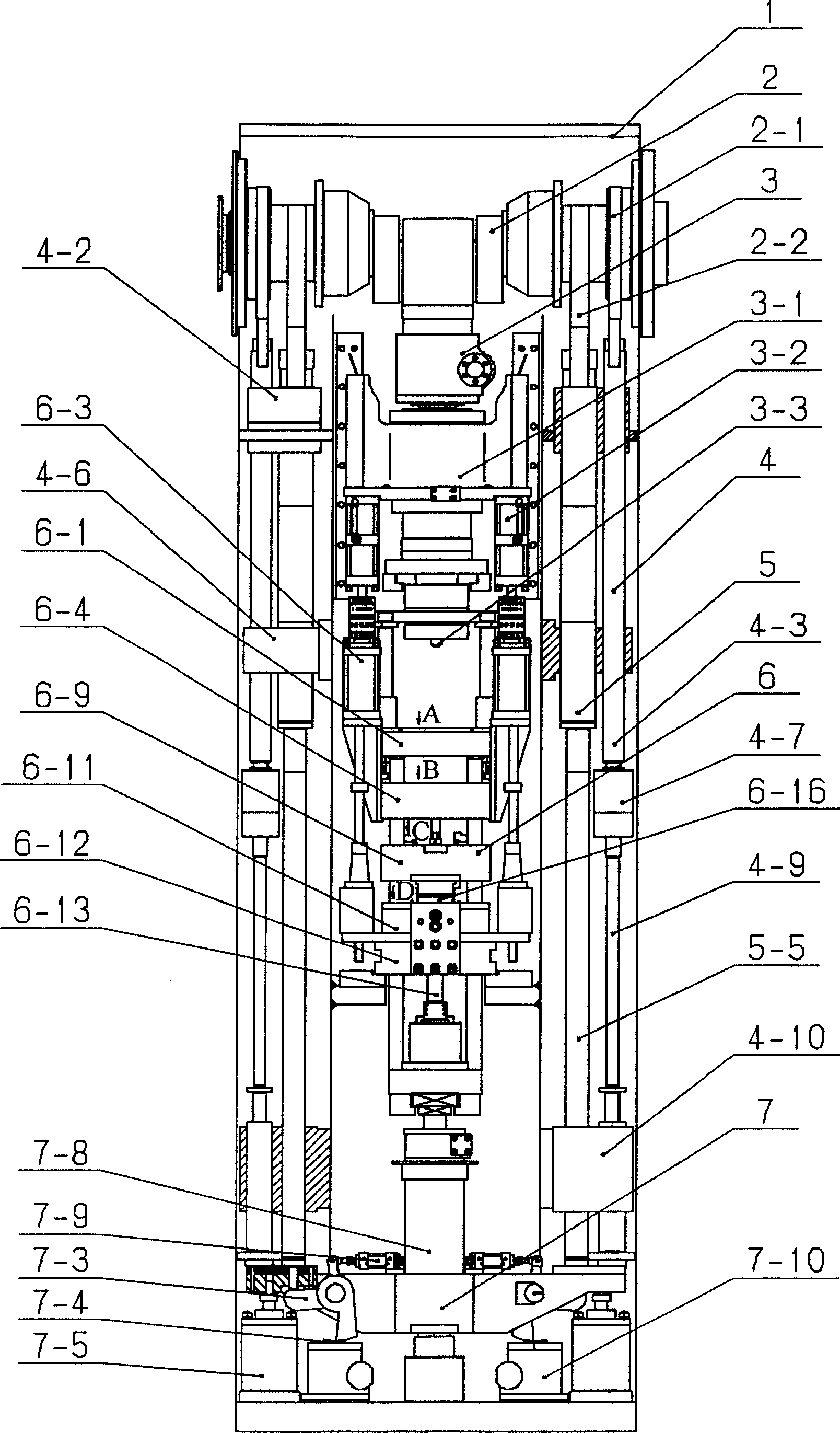
[0020] Crankshaft 2 is installed on the horizontal position above the frame 1, symmetrical, two pairs of ejection cams 2-2 and pressurization cams 2-1 are installed on both sides of crankshaft 2, and pressurization cam 2-1 cooperates with pressure rod 4 to eject the mold Cam 2-2 cooperates with ejection lever 5.

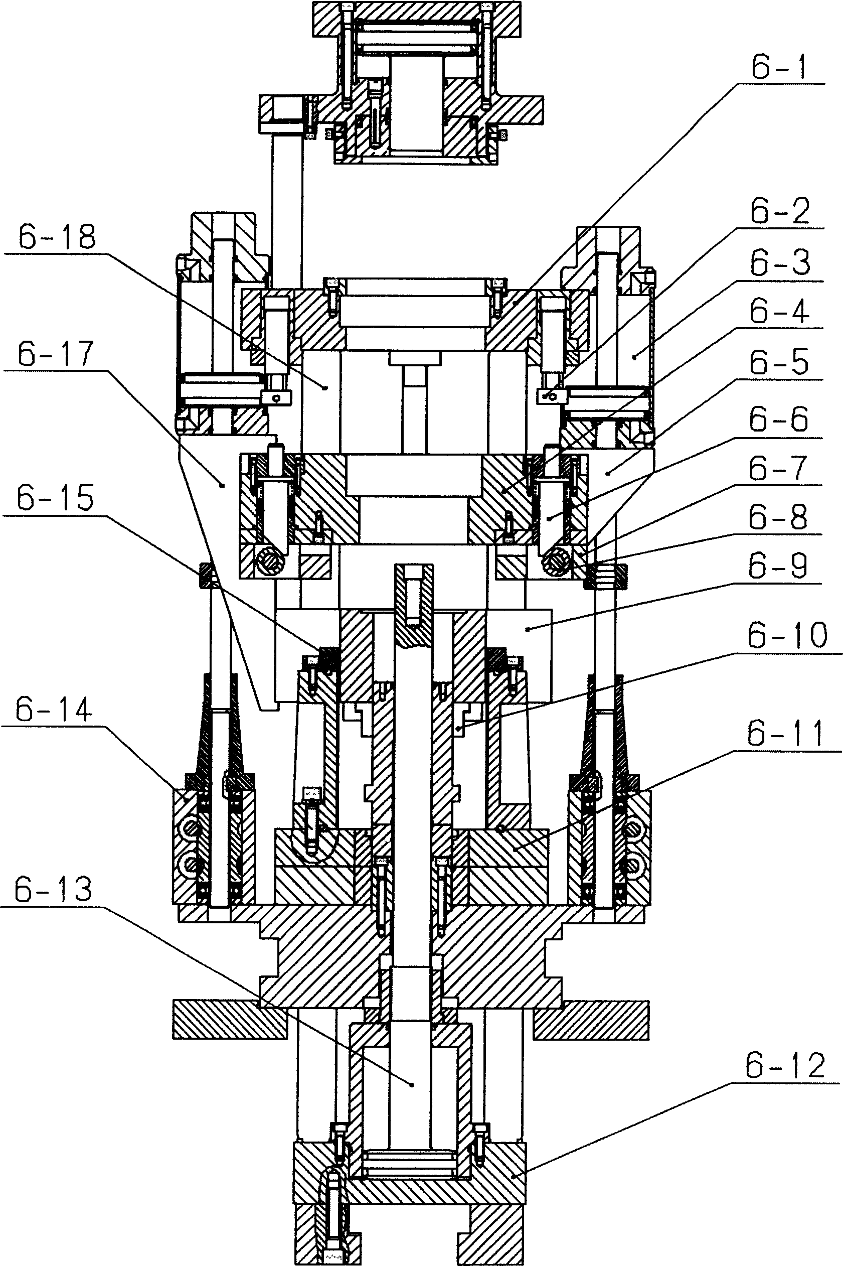
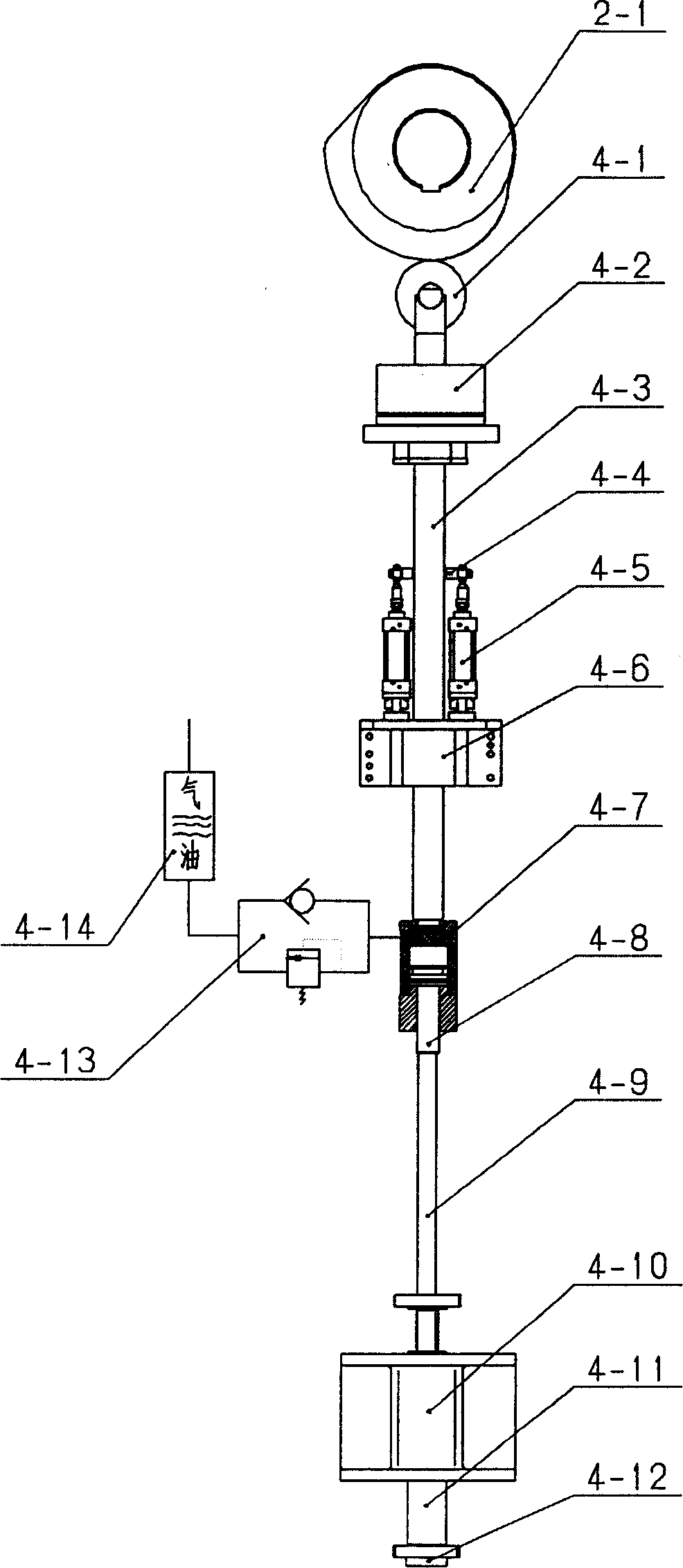
[0021] The pressure rod 4 is movably connected into one by the upper pressure rod 4-3 and the lower pressure rod 4-9 through the oil cylinder body 4-7 and the piston rod 4-8, and the oil cylinder body 4-7 is connected with the pressure regulating valve 4-13, gas-liquid Conversion cylinder 4-14 connection. Connect a roller 4-1 with pivot pin at the top of pressure bar 4, and the upper end and the middle part of upper pressure bar 4-3 slide and are equipped with upper axle seat 4-2, lower axle seat 4-6. Respectively install a cylinder 4-5 o...


PUM


Abstract

The invention is a powder shaping machine which includes a force transmitting mechanism with two symmetric pressure, demoulding rod respectively fits with the pressing and demoulding cams. The connecting rod links together in turn a low mould plate, once and twice plate, pressing head base, and the soleplate. The once and twice pressing plate each has two pressing rods fitting with the pushing rod corresponds upon the low mould plate at the upper side and with the roller in the pressing block at the lower side. The pressing block fits with corresponding positive block fixed on the pressing head base. The cylinder linked with once, twice pressing plate fits with the cylinder on the flexural slipping mechanism base forming the mould stand pressing mechanism. The swing block links with the cylinder on the bridging arm and fits with the block fixed on the block box on the stand and the pushing rod on the bridging arm. The cylinder on the machine stand fits with the bridging arm forming the demoulding mechanism. The structure is simpler by leave off the original intermediate swing arm and the dual force transmitting mechanism transmits the force uniformly safely and stably especially suitable for large shaping machine of large tonnage with a product of uniform intensity at every steps.

Description

technical field [0001] The invention relates to a mechanical processing equipment, a powder molding machine. Background technique [0002] Because the powder molding machine can automatically and continuously press powder metallurgy parts with high precision and good finish at one time, it saves a lot of raw materials and processing time for less and no cutting processing, and has a wide range of applications, so it is favored by enterprises. [0003] However, the widely used powder molding machine still has some shortcomings, that is, it can only press products with simple and single shapes, but cannot press products with complex shapes, especially those with steps, deep holes or even multiple steps. , In addition, its pressed products also have the disadvantage that the upper and lower densities are extremely inconsistent. There is also an improved powder molding machine on the market. Although the pressing process has been improved to improve the pressing quality of simp...

Claims


Application Information

Patent Timeline
IPC IPC(8): B30B11/00
Inventor 严培义严俏敏
Owner 严培义
Learn More