Intelligent type heat pump water heater

A heat pump water heater, an intelligent technology, is applied in the directions of fluid heaters, household heating, heating methods, etc., can solve the problems of insufficient preheating time, unstable performance of the heat pump water heater, etc., and achieves long service life, low cost, and simple operation. Effect

Inactive Publication Date: 2005-06-29
SHANGHAI JIAO TONG UNIV
0 Cites 28 Cited by

AI-Extracted Technical Summary

Problems solved by technology

[0004] The purpose of the present invention is to address the deficiencies of the prior art and provide an intelligent heat pump water heater. The user can not only set operating parameters such as timing and constant temperature, and choose among various heat pump water heater working m...

Abstract

An intelligent heat pump water heater is composed of a compressor, an evaporation coil, a fan, an electronic expansion valve, a condensing coil and a living water tank to form a conventional heat pump water heater system, and its operating state is regulated by an intelligent control device. The intelligent control device collects the water tank temperature, ambient temperature, and evaporator inlet and outlet temperature, and performs automatic control according to the operating parameters set by the user and the selected intelligent mode, normal mode, midday mode, valley power mode, midday plus valley power mode or instant heating mode adjust. When the system is running in the intelligent mode, it can infer the user's water consumption habits according to the fuzzy rules according to the regularly stored water consumption information, so as to automatically adjust the set temperature and heating time of the water tank, so that the system can achieve the best work in any season. performance. The invention effectively solves the problems of unstable performance and insufficient preheating time of the heat pump water heater, and has the advantages of low cost, high efficiency and energy saving, safety and reliability, long service life, simple operation and the like.

Application Domain

Technology Topic

Image

  • Intelligent type heat pump water heater
  • Intelligent type heat pump water heater
  • Intelligent type heat pump water heater

Examples

  • Experimental program(1)

Example Embodiment

[0016] The technical solution of the present invention will be further described below in conjunction with the accompanying drawings.
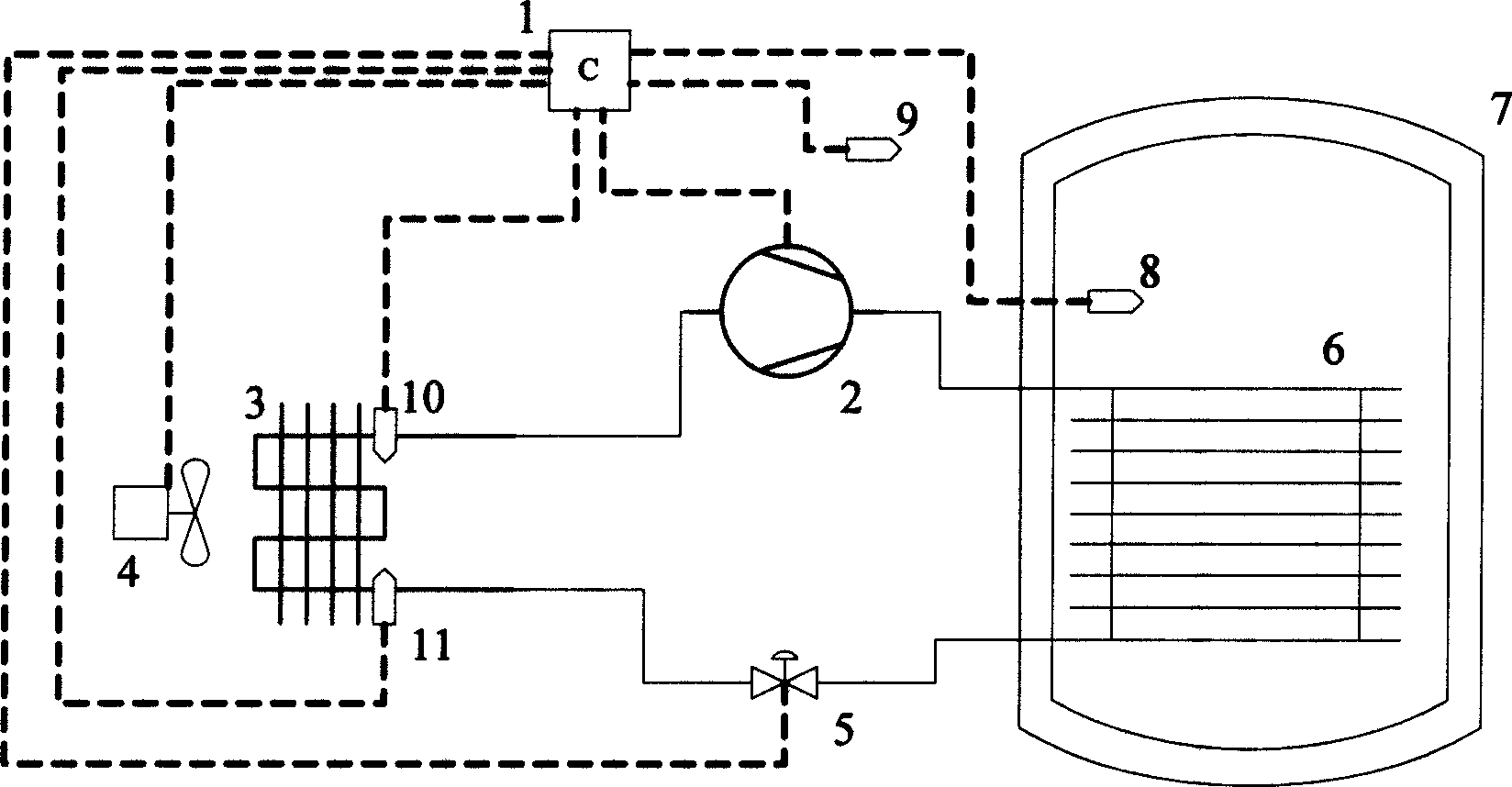
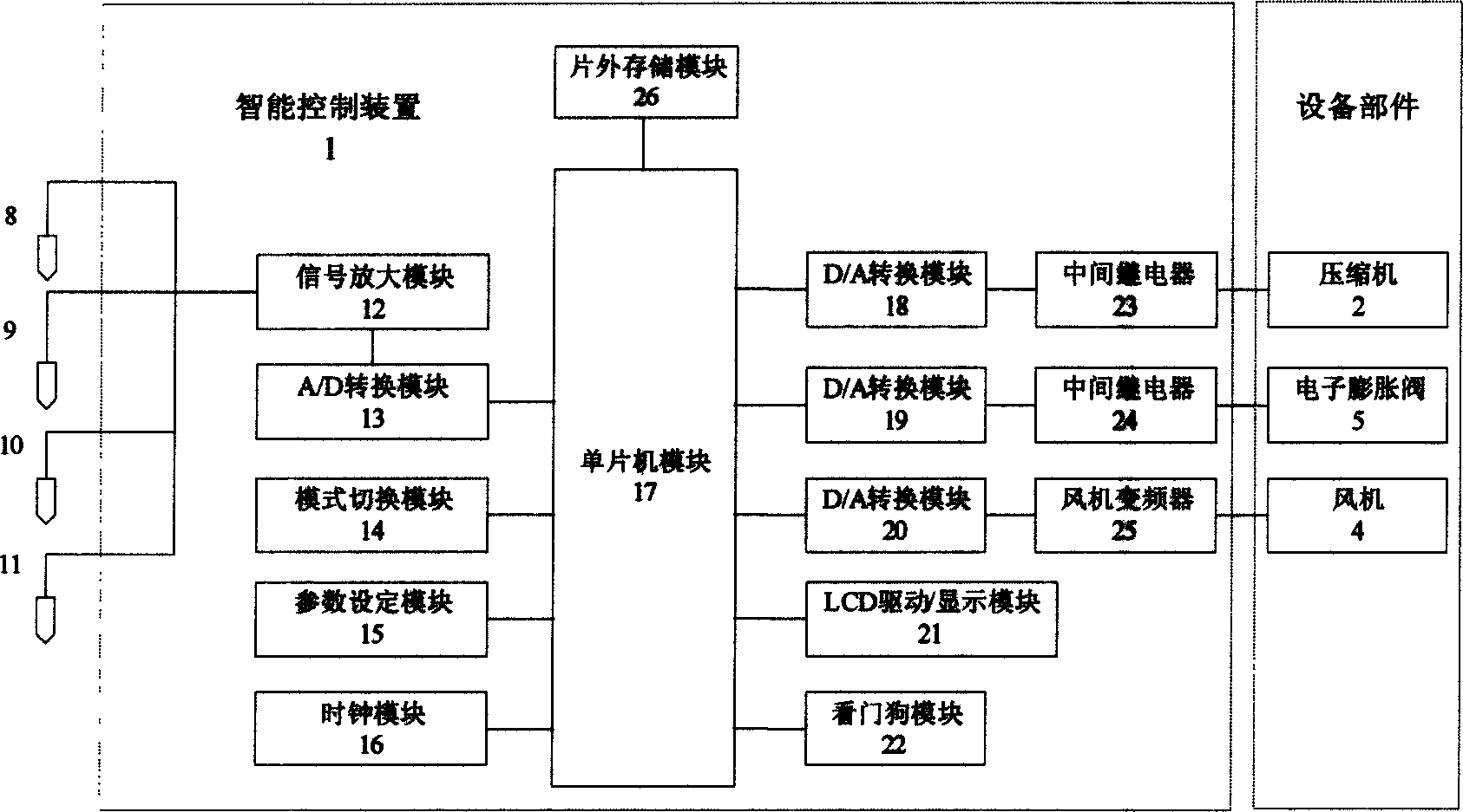
[0017] The overall structure of the present invention is as figure 1 As shown, the intelligent heat pump water heater is composed of a compressor 2, an evaporating coil 3, a fan 4, an electronic expansion valve 5, a condensing coil 6 and a living water tank 7 to form a conventional heat pump water heater system, and its operating state is regulated by the intelligent control device 1. The water tank temperature sensor 8 is installed in the middle of the living water tank 7 to monitor the temperature of the hot water in the tank, and the ambient temperature sensor 9 is installed in the outdoor space where the evaporator coil 3 is located to monitor the ambient temperature. The evaporator inlet temperature sensor 11 and the evaporator outlet The temperature sensors 10 are respectively arranged on the inlet and outlet pipes of the evaporating coil 3 to monitor the superheat of the refrigerant and the frosting condition of the evaporating coil 3. The output signals of the water tank temperature sensor 8, the ambient temperature sensor 9, the evaporator inlet temperature sensor 11, and the evaporator outlet temperature sensor 10 are all connected to the intelligent control device 1. The output of the intelligent control device 1 is connected to the compressor 2, the fan 4, and the electronic The expansion valve 5 is connected to control them.
[0018] The structure of the intelligent control device 1 is as follows figure 2 As shown, it mainly includes water tank temperature sensor 8, ambient temperature sensor 9, evaporator inlet temperature sensor 11, evaporator outlet temperature sensor 10, off-chip memory 26, signal amplification module 12, A/D conversion module 13, and mode switching module 14. , Parameter setting module 15, clock module 16, single chip microcomputer 17, D/A conversion module 18, 19, 20, LCD drive/display module 21, watchdog module 22, intermediate relay 23, 24, fan inverter 25, etc.
[0019] The output ends of the water tank temperature sensor 8, the ambient temperature sensor 9, the evaporator inlet temperature sensor 11, and the evaporator outlet temperature sensor 10 are connected to the input end of the signal amplification module 12, and the output end of the signal amplification module 12 is connected to the A/D conversion module 13 The output terminals of the mode switching module 14, the parameter setting module 15, the clock module 16, and the A/D conversion module 13 are connected to the input terminal of the single-chip computer 17, and the output terminal of the single-chip computer 17 is respectively connected to the D/A conversion of the control compressor signal The input terminals of the module 18, the D/A conversion module 19 for controlling the electronic expansion valve signal, the D/A conversion module 20 for controlling the fan signal, the LCD driving/display module 21, and the watchdog module 22 are connected, and at the same time, the off-chip memory 26 The output terminal of the D/A conversion module 18 that controls the compressor signal is connected to the compressor 2 through the intermediate relay 23, and the output terminal of the D/A conversion module 19 that controls the electronic expansion valve signal is connected to the compressor through the intermediate relay 24. The electronic expansion valve 5 is connected, and the output end of the D/A conversion module 20 that controls the fan signal is connected to the fan 4 through the fan frequency converter 25, thereby controlling the operation of the heat pump water heater equipment.
[0020] The control flow of the present invention is as image 3As shown, after the power is turned on, a multi-point temperature acquisition probe composed of a water tank temperature sensor 8, an ambient temperature sensor 9, an evaporator inlet temperature sensor 11, and an evaporator outlet temperature sensor 10 monitors the temperature of each point, and uses the signal amplification module 12 Amplify, and then the A/D conversion module 13 converts the analog signal into a digital signal and inputs it into the ROM of the single-chip microcomputer 17. The user can set the parameters including the set temperature, clock, timing and other parameters through the parameter setting module 15 as needed, and pass the mode switch module 14 Switch the working mode of the heat pump water heater, the microcontroller 17 collects the digital signal of the clock module 16 and updates the clock data in real time. The microcontroller 17 periodically sends the dog feed signal to the watchdog module 22 to maintain the normal operation of the microcontroller and send the display signal to the LCD driver. Display module 21 to update the display data. When the user does not operate in the smart mode, he can choose the working modes including normal mode, noon mode, valley power mode, noon plus valley power mode and instant heating mode. The smart control device 1 will be based on the different heating periods of curing and the settings set by the user. Set the temperature to heat the domestic water. The water tank temperature sensor 8, the ambient temperature sensor 9, the evaporator inlet temperature sensor 11, and the evaporator outlet temperature sensor 10 continue to monitor; when the user adopts the intelligent control mode, the temperature digital signal and off-chip memory The user water information stored periodically and automatically in 26 is input into the ROM of the single-chip microcomputer 17, and the solidified calculation program is called for calculation, and finally the best set temperature and best heating period are obtained. If the current time is not in the optimal heating period or the water tank temperature exceeds the optimal set temperature, the heat pump water heater is in standby mode. If the current time is within the optimal heating period and the water tank temperature is lower than the optimal set temperature, the system starts to judge the evaporation coil 3 cooling load and ideal refrigerant flow, the adjustment signal is transformed by the D/A conversion module 18 that controls the compressor signal, the D/A conversion module 19 that controls the electronic expansion valve signal, and the D/A conversion module 20 that controls the fan signal As an analog signal, the analog signal is respectively input to the intermediate relays 23 and 24 and the fan inverter 25 to control the compressor 2, the electronic expansion valve 5 and the fan 4 in the heat pump water heater equipment. When increasing the water temperature of the water tank, the single-chip microcomputer 17 controls and adjusts one or more of the compressor 2, the electronic expansion valve 5 and the fan 4 according to the environmental parameters, the water tank temperature sensor 8, the ambient temperature sensor 9, and the evaporator inlet temperature sensor 11, The evaporator outlet temperature sensor 10 continues to monitor. In addition, the single-chip microcomputer 17 periodically collects the water temperature of the water tank, blurs it into the user's water consumption habits, and saves the processing result in the off-chip memory 26, so that the set temperature and heating time can be judged by combining the real-time ambient temperature in the smart mode.

PUM

no PUM

Description & Claims & Application Information

We can also present the details of the Description, Claims and Application information to help users get a comprehensive understanding of the technical details of the patent, such as background art, summary of invention, brief description of drawings, description of embodiments, and other original content. On the other hand, users can also determine the specific scope of protection of the technology through the list of claims; as well as understand the changes in the life cycle of the technology with the presentation of the patent timeline. Login to view more.

Similar technology patents

Classification and recommendation of technical efficacy words

  • Extended service life
  • Easy to operate
Why Eureka
Try Eureka