

Control device for hydraulic winch
一种液压绞车、控制装置的技术,应用在流体压力致动装置、卷扬装置、发条的机构等方向,能够解决不能速度控制范围大一些等问题,达到改善响应性的效果
- Summary
- Abstract
- Description
- Claims
- Application Information
AI Technical Summary
Problems solved by technology
Method used
Image

Examples
Embodiment approach 1
[0039] Embodiment 1 (refer to Fig. 1~ image 3 )
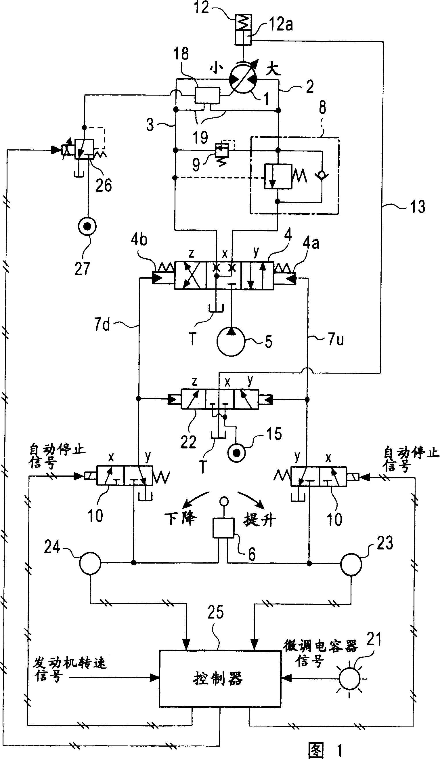
[0040] In FIG. 1 , reference numeral 1 is a variable capacity hydraulic motor as a drive source of a winch. The lifting side and lowering side pipelines 2, 3 of the hydraulic motor 1 are connected to a hydraulic pump 5 through a hydraulically controlled switching control valve 4 having three positions X, Y, and Z of neutral, lifting, and lowering. The control valve 4 controls the supply and discharge of hydraulic oil to the hydraulic motor 1 (drive, stop, rotation direction and speed of the hydraulic motor 1 ).
[0041] Indicated at 6 is a remote control valve as an operating mechanism for operating the control valve 4 on the lifting side or the lowering side. The remote control pressure corresponding to the operation amount of the remote control valve 6 is sent to the control ports 4a and 4b on the control valve 4 on the control valve 4 through the two remote control pressure lines 7u and 7d on the control valve 4 .
[004...
Embodiment approach 2
[0073] Embodiment 2 (refer to Figure 4 )
[0074] Only points of difference from Embodiment 1 will be described.
[0075] In Embodiment 1, hydraulic pressure is supplied from the regulator hydraulic pressure source 27 to the regulator 18 through the regulator control valve 26 . Therefore, as a phenomenon that is likely to occur in the solenoid valve, if the regulator control valve 26 fails on the small-capacity command side, the regulator 18 does not operate on the large-capacity side at the time of automatic stop.
[0076] Therefore, in Embodiment 2, the hydraulic pressure source introduction port 26 a of the regulator control valve 26 is connected to the pressure chamber 12 a of the negative brake 12 .
[0077] With this configuration, even if the regulator control valve 26 fails on the small displacement side, the hydraulic pressure in the pressure chamber 12a is released when the negative brake 12 performs the braking operation, so the regulator control valve 26 becomes...
Embodiment approach 3
[0078] Embodiment 3 (see FIG. 5 )
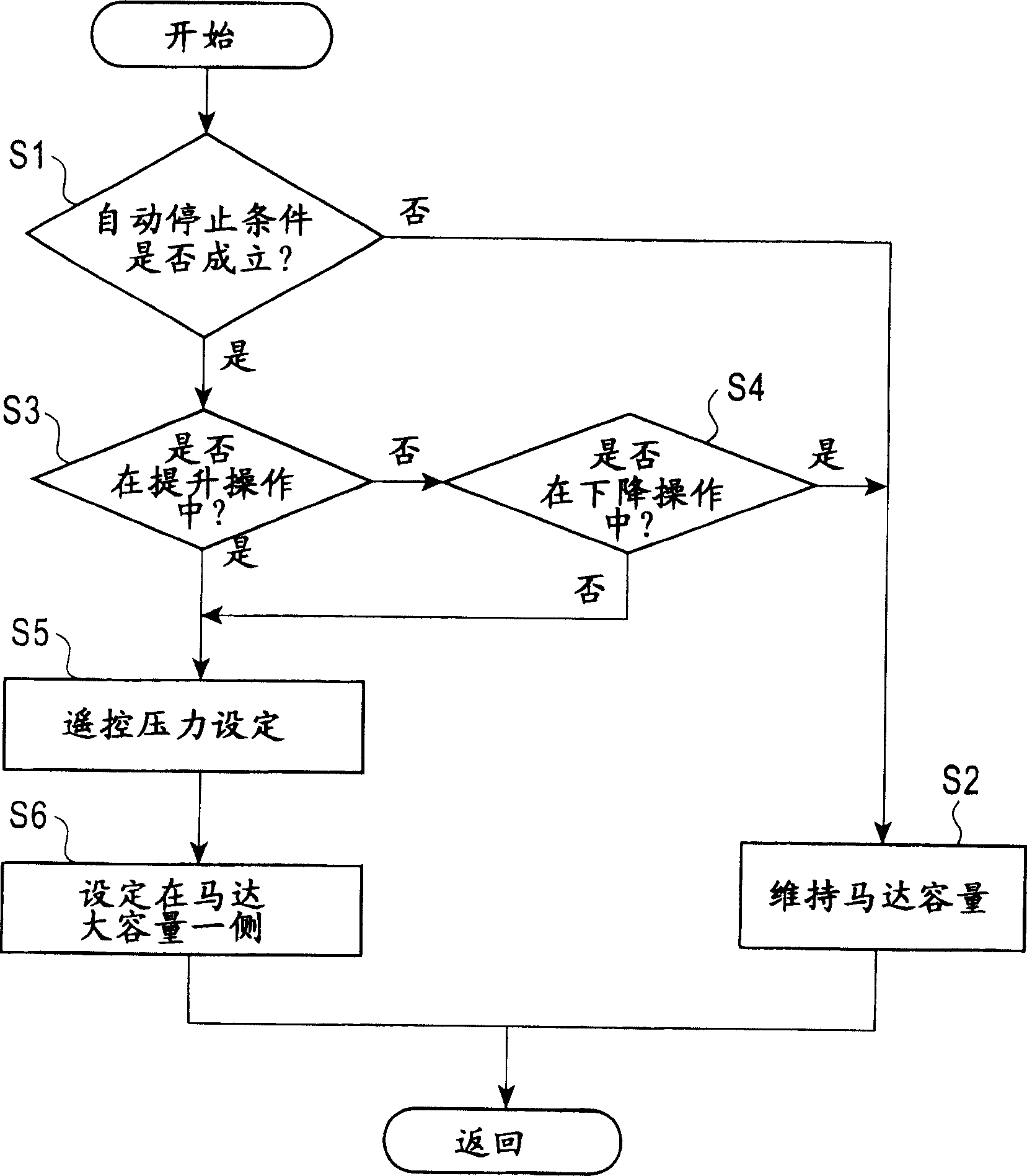
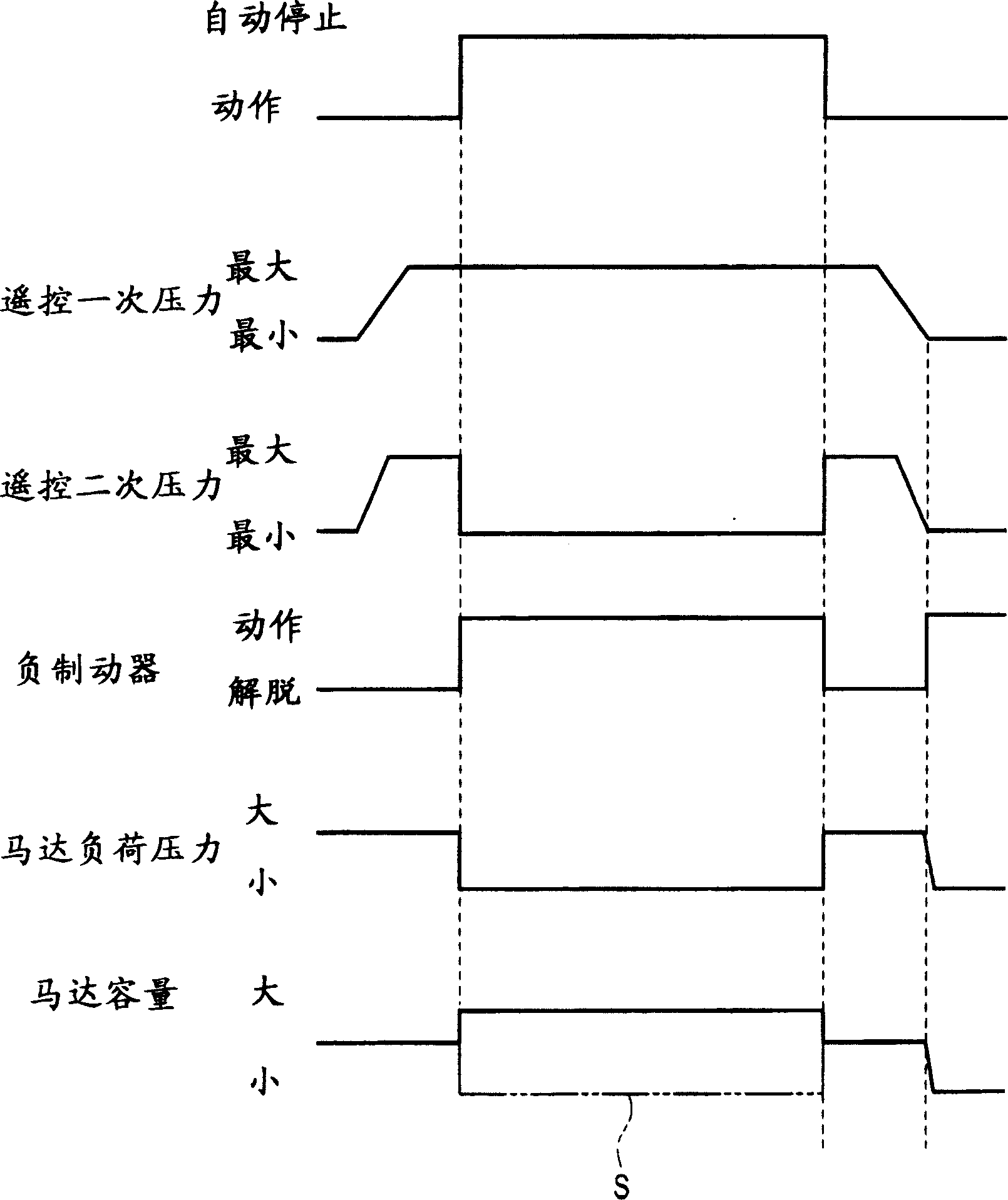
[0079] In Embodiments 1 and 2, a configuration is set such that a large capacity command signal is output from the controller 25 to the regulator control valve 26 simultaneously with the operation of the negative brake 12 at the time of automatic stop, and the hydraulic motor 1 is driven according to the signal. Set to large capacity. On the other hand, in Embodiment 3, the hydraulic motor 1 is set to a large capacity by shutting off the operation signal of the remote control valve 6 , that is, the remote control pressure at the time of automatic stop.
[0080] To describe in detail, it is assumed that the remote control pressure lines 7u and 7d on both sides are connected to the regulator 18 through the electromagnetic switching valve 28 controlled by the shuttle valve 17 and the controller 25, and the remote control pressure extraction line 29. , the larger the operation amount of the remote control valve 6 is, the smaller the motor capac...
PUM
 Abstract
Description
Claims
Application Information