
Bi-directional thruster pig apparatus and method of utilizing same

A pig and pipeline technology, which can be used in cleaning appliances, driving devices for drilling in wellbore, drilling pipes, etc., and can solve problems such as restricting pipeline movement and cleaning ability.

Inactive Publication Date: 2005-07-13
SUPERIOR ENERGY SERVICES LLC
View PDF4 Cites 17 Cited by
  • Summary
  • Abstract
  • Description
  • Claims
  • Application Information

AI Technical Summary

Problems solved by technology

This device, although effective, cannot be used to allow the device to continue moving forward in the pipeline while obstructions in the pipeline are being cleared
Also, unlike the present invention, the pressurized fluid is injected through the holes of the coil via a single nozzle at the front end of the pig, which limits its movement and cleaning ability in the pipeline

Method used


Image

  • Bi-directional thruster pig apparatus and method of utilizing same
  • Bi-directional thruster pig apparatus and method of utilizing same
  • Bi-directional thruster pig apparatus and method of utilizing same

Examples


Embodiment Construction

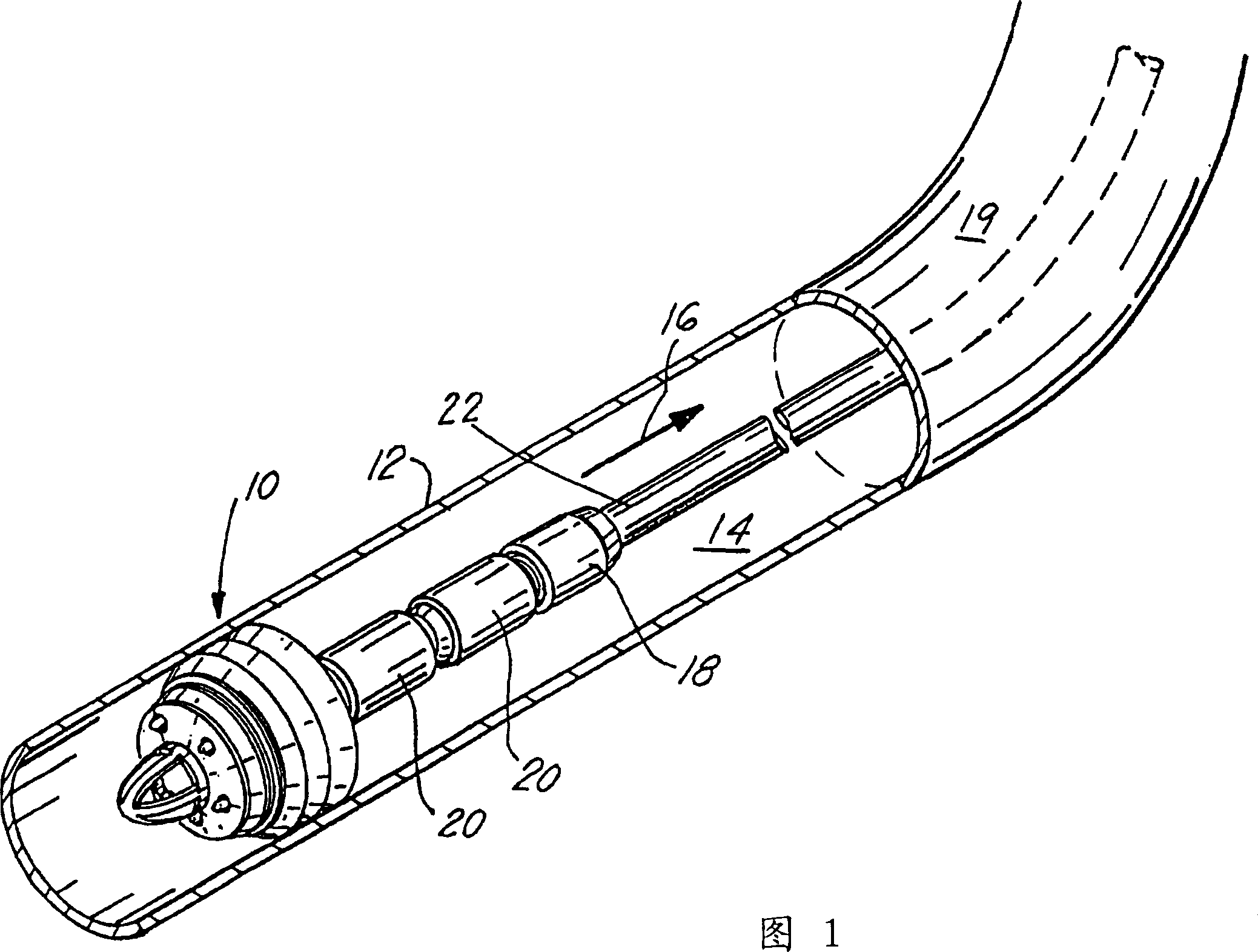
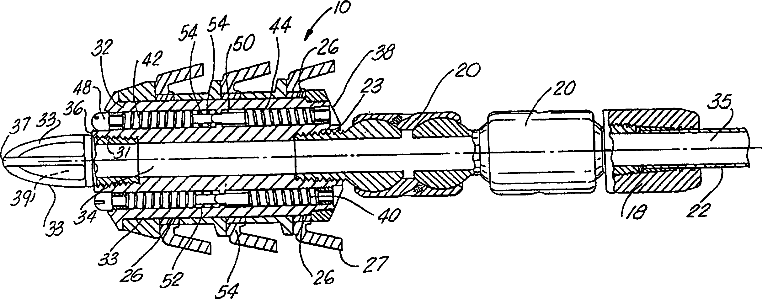
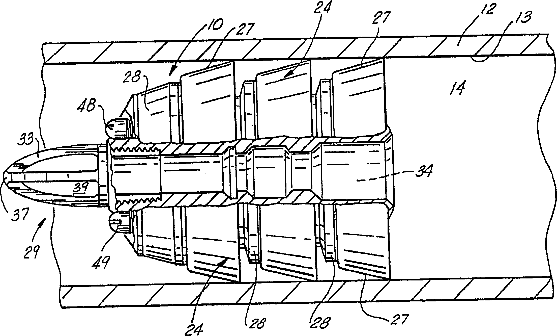
[0041] Figures 1 to 12 illustrate a preferred embodiment of the device of the present invention and its method of use. As shown generally in cross-section in FIG. 1 , there is shown a propulsion pig assembly 10 , hereafter generally referred to simply as assembly 10 , disposed in a pipeline 12 which is typically drilled vertically, horizontally, or a combination of both. Sectional piping or casings of 50,000 or 60,000 thousand feet (15 or 18 km) or more in length to recover hydrocarbons to the surface through holes 14 of the piping in the direction of arrow 16. The duct shown comprises a continuous circular wall portion 19, and has, as described above, a bore 14 therethrough. As shown in FIG. 1, the pig assembly 10 is installed at the end of a length of serpentine 22, which is common in the oil and gas industry. A coil 22 is known in the art as a continuous length of flexible tubing that is unwound on a spool on a drilling platform and allows the coil to be continuously lower...


PUM


Abstract

A retrievable pig apparatus having a substantially cylindrical body portion, the body portion having a central flow bore therethrough, and secured to coiled tubing, including a central fluid flow bore in fluid communication with the interior bore of the coiled tubing; a plurality of flow bores spaced equally apart within the body, with the flow bores allowing fluid flow to be injected at a certain predetermined pressure through the flow bores, so as to be emitted on the front end of the pig for defining a high pressure spray of fluid or the like material to break up blockages of debris in the pipeline, such as paraffin or the like; the debris retrieved through the central bore back into the coiled tubing to be stored in a tank or the like on the surface. There is further included a plurality of flexible cups, spaced apart along the outer wall of the pig body, each cup secured to an interior metallic ring around the body of the pig, with the flexible cups making contact with the wall of the pipeline so as to provide a continuous fluid seal between the wall of the pipeline and the ends of the plurality of flexible cups. Intermediate each cup there is provided a compressible safety ring, which will compress under excess pipeline pressure, thus allowing the fluid to flow past the plurality of flexible cups, reducing the pressure in the pipeline. Further there is provided within the plurality of six flow bores around the interior flow bore, for adjusting the force that is allowed to flow through the plurality of bores in either direction by providing a first and second thruster springs of a pre-determined compressible force for allowing the spring to be compressed and effecting fluid flow therethrough in the direction in which the flow is to travel in the bores.

Description

technical field [0001] The device of the invention relates to a device for inserting a pipe along a pipeline, well or open hole. More specifically, the present invention relates to a bi-directional propulsion pig device capable of inserting a serpentine pipe along a pipeline in deep water to maintain the pipeline and remove such as ozokerite, hydrate, pipe scale, and other solid debris Obstacles are removed. The pipeline may be a vertical or horizontal well, part of a pipeline, or a combination of both. More particularly, the device and method of use of the present invention provide a two-way propulsion system by using a replaceable, adjustable double-acting check valve, the hydraulic propulsion pressure is preset and determined before work or Live changes. The bi-directional fluid flow feature of the device allows the device to be withdrawn from the pipeline after it has completed its cleaning function by eliminating or reducing the hydraulic or static pressure on the pig ...

Claims


Application Information

Patent Timeline
Patent Type & Authority Applications(China)
IPC IPC(8): E21B4/18E21B17/10E21B23/08E21B37/00
CPCE21B4/18E21B17/1014E21B17/1057E21B23/08E21B37/00
Inventor 詹姆斯·R·克劳福德
Owner SUPERIOR ENERGY SERVICES LLC
Learn More