Method for detecting angular difference and apparatus for controlling synchronous motor

A technology of synchronous motor and detection method, which is applied in the direction of motor generator control, AC motor control, single motor speed/torque control, etc., can solve problems such as long time, high price, vibration, etc., to prevent vibration, shorten time, Effect of preventing vibration phenomenon

Inactive Publication Date: 2005-07-20
FANUC LTD
View PDF1 Cites 11 Cited by
  • Summary
  • Abstract
  • Description
  • Claims
  • Application Information

AI Technical Summary

Problems solved by technology

The problem with the Hall element is that it cannot be used for rectangular wave drive because it only detects the phase position. Although the absolute value encoder is suitable for sine wave drive, it has the problem of high price.
There are two problems arising from this. The first problem is that it takes a long time for the rotor of the motor to stop.
The second problem is the vibration phenomenon caused by not stopping at the magnetic pole position when the friction of the rotor is small
[0012] In addition, although the method described in the above-mentioned patent document 3 is to solve the second problem of the vibration phenomenon caused by the failure of the rotor to stop at the magnetic pole position when the friction is small, it does not solve the problem of stopping the rotor of the motor. Whereas the method for the first problem that takes longer

Method used


Image

  • Method for detecting angular difference and apparatus for controlling synchronous motor
  • Method for detecting angular difference and apparatus for controlling synchronous motor
  • Method for detecting angular difference and apparatus for controlling synchronous motor

Examples


Embodiment Construction

[0031] Hereinafter, the angle difference detection method and the synchronous motor control device of the present invention will be described with reference to the drawings.

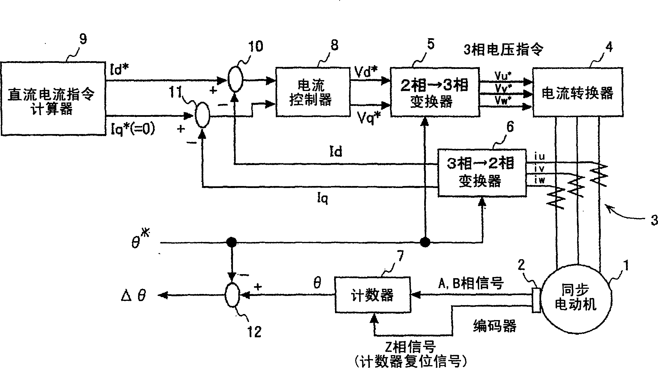
[0032] figure 1 It is a schematic diagram for briefly explaining the control apparatus of the synchronous motor of this invention. figure 1 The symbol 1 in the symbol is a permanent magnet synchronous motor, and the incremental encoder 2 outputs the rotation of the permanent magnet synchronous motor 1, detects the direction of forward rotation and reverse rotation, and the position A and B phase signals in one revolution, and as a rotation The Z-phase signal of the reference position signal is output once per revolution.

[0033] Here, the permanent magnet synchronous motor 1 and the incremental encoder 2 are in a state where the rotor magnetic pole position of the synchronous motor 1 does not match the reference position of the encoder.

[0034] In addition, in the figure, symbol 3 is a current detect...


PUM


Abstract

Disclosed is a method for detecting an angular difference between a motor magnetic pole position and an encoder reference position in a permanent magnet synchronous motor equipped with an incremental encoder, wherein a DC current command for supplying a monotonically decreasing DC current is applied to the permanent magnet motor for DC excitation, and the angular difference is detected by detecting an amount of rotor movement due to the DC excitation by using the incremental encoder. By applying a DC excitation current command for supplying a monotonically decreasing DC current rather than supplying a DC current of constant magnitude as in the prior art, it becomes possible, without estimating the initial magnetic pole position, to shorten the time required for the motor rotor to stop, while preventing the phenomenon in which the rotor does not stop at the magnetic pole position but oscillates around that position.

Description

technical field [0001] The invention relates to an angle difference detection method for detecting the angle difference between the motor magnetic pole position and the encoder reference position of a permanent magnet synchronous motor with an incremental encoder and a control device for the synchronous motor using the angle difference detection method. Background technique [0002] The permanent magnet synchronous motor operates by detecting the magnetic pole position of a rotor equipped with a permanent magnet with a detector, and passing a current corresponding to the detection signal through the armature winding. [0003] As detectors for detecting the magnetic pole position of the rotor, Hall elements, absolute encoders, and incremental encoders are known. The problem with the Hall element is that it cannot be used for rectangular wave driving because it only detects the phase position. Although the absolute value encoder is suitable for sine wave driving, it has the pr...

Claims


Application Information

Patent Timeline
Patent Type & Authority Applications(China)
IPC IPC(8): H02P6/16H02P6/06H02P6/08H02P6/28H02P25/02
CPCH02P25/023H02P3/025H02P21/0092H02P21/36H02P25/03
Inventor 岩下平辅秋山隆洋手塚淳一
Owner FANUC LTD
Why Eureka
Try Eureka