Axial workpiece bending deformed planar array CCD measuring method and apparatus

A shaft part and bending deformation technology, which is applied in the field of bending deformation measurement of parts, can solve the problems of few detection points and low measurement accuracy, and achieve the effects of simple equipment, high measurement accuracy and fast measurement speed.

Inactive Publication Date: 2005-07-27
SOUTH CHINA UNIV OF TECH
View PDF0 Cites 28 Cited by
  • Summary
  • Abstract
  • Description
  • Claims
  • Application Information

AI Technical Summary

Problems solved by technology

[0003] The object of the present invention is to provide a kind of area array CCD (Charge Coupled Devices , charge coupled device) method and device for measuring bending deformation of shaft parts

Method used


Image

  • Axial workpiece bending deformed planar array CCD measuring method and apparatus

Examples


Embodiment 1

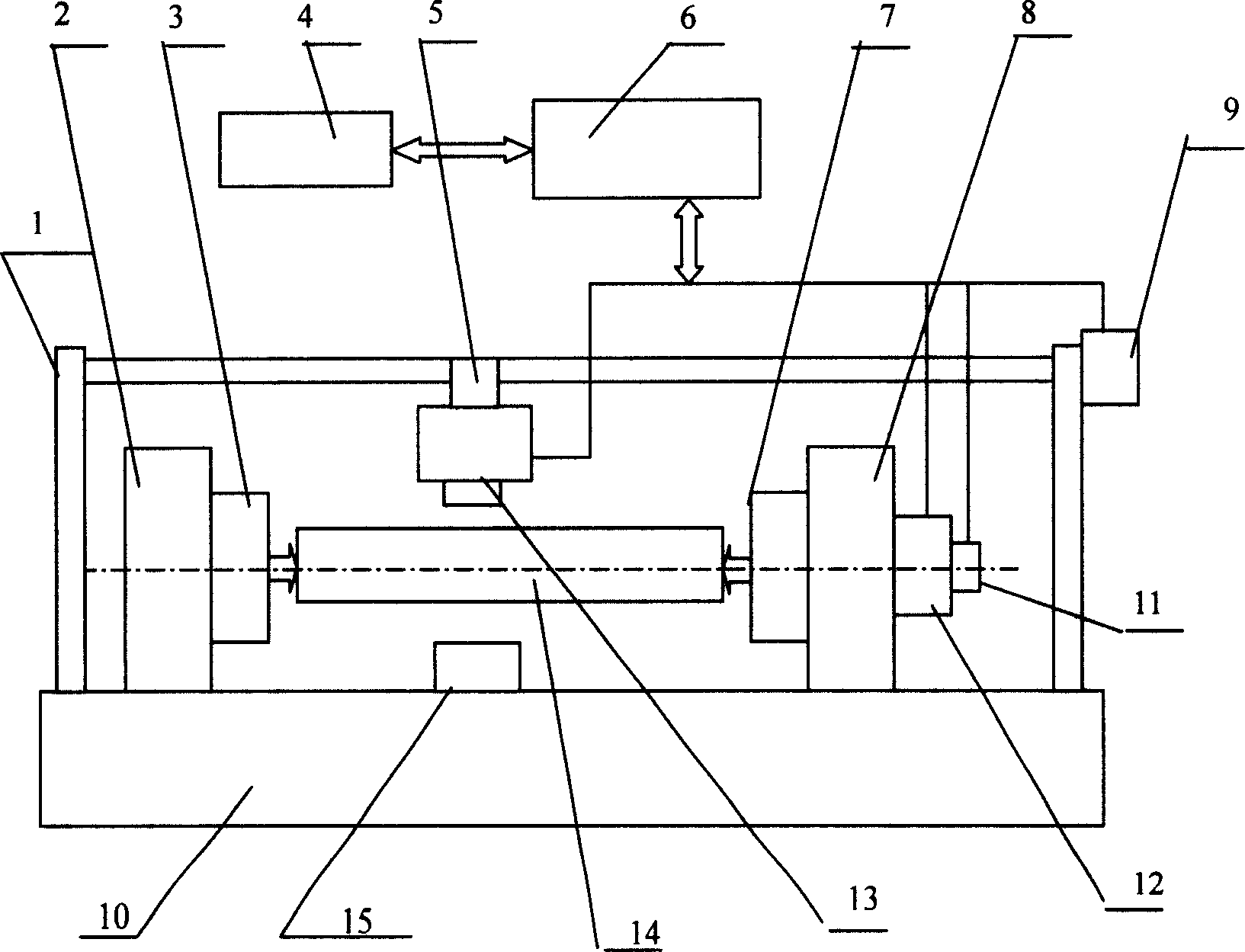
[0019] Such as figure 1 As shown, the shaft part to be measured is a long shaft, and the long-axis bending deformation area array CCD measuring device includes an image acquisition and processing system, and a rotation control system of the measured long shaft. The image acquisition and processing system and the rotation control system of the measured shaft parts are mounted on the frame 10 of the straightening machine. The image acquisition and processing system includes an area array CCD13, a backlight source 15, an I / O card 6, and an industrial computer 4. The measured long axis is supported by the top 3 and the top 7, the tailstock 2 and the gearbox 8 are fixed on the straightening machine frame 10, and the area array CCD 13 and the backlight 15 are respectively placed on both sides of the measured long step axis. The area array CCD13 is connected with the stepping motor 9 and located on the ball screw pair 5, and the stepping motor 9 drives the ball screw pair 5 to move ...

Embodiment 2

[0021] The shaft parts to be tested are three-step shaft parts. One area array CCD is used on each step, and a total of three area array CCDs are used to connect with the ball screw pairs respectively. The three ball screw pairs are connected with the support frame 1 and also connected with the stepping motor 9. The stepper motor 9 drives three area array CCDs 13 to move axially along the measured three-step shaft part, and continuously collects image data of different shaft diameters. Other devices are the same as Example 1, and the measurement method is also the same as Example 1.


PUM


Abstract

A method for measuring the bending deflection of shaft parts includes using a planar array to collect image data of shaft parts, sending collected data to I/O card and then to process control computer for obtaining deflection parameter of the shaft parts after data is processed. The device for realizing the method consists of image collection and process system including planar array CCD, back light source, I/O card and process control computer as well as parts rotary control system including gear box, stepping motor and coder.

Description

technical field [0001] The invention relates to a method for measuring the bending deformation of a part, especially a method for measuring the bending deformation of a shaft part with an area array CCD. The invention also relates to a measuring device for the bending deformation of a shaft part. Background technique [0002] In the process of mechanical manufacturing, shaft parts will have bending deformation after cutting or heat treatment. Straightening the bending deformation of shaft parts is an important process in the machining process. High-precision alignment reduces finishing allowances and reduces scrap rates. The measurement method and measurement accuracy of bending deformation are the key to straightening shaft parts. The straightening machine is mainly used to complete the straightening processing of shaft parts such as shafts, tubes, and rods. The straightening machine detection system should be able to accurately detect the bending deformation and deformat...

Claims


Application Information

Patent Timeline
Patent Type & Authority Applications(China)
IPC IPC(8): G01B11/16G01B21/32
Inventor 吴上生
Owner SOUTH CHINA UNIV OF TECH
Why Eureka
Try Eureka