Laser Raman sample pool for gas analysis

A gas analysis and sample cell technology, which is used in the analysis of materials, material excitation analysis, and material analysis by optical means. It can solve problems such as low collection efficiency, difficult installation, and loose structure, and achieve improved collection efficiency and good sealing , compact structure

Active Publication Date: 2005-07-27
上海众毅工业控制技术有限公司
View PDF1 Cites 10 Cited by
  • Summary
  • Abstract
  • Description
  • Claims
  • Application Information

AI Technical Summary

Problems solved by technology

Since it is not fixedly installed on the spectrometer, the structure is loose, it is difficult to install, and it cannot be used in practical situations outside the laboratory
At the same time, from the design principle, its collection efficiency is low
In the current gas detection based on Raman technology, it is difficult to rely on conventional gas sample cells to achieve the sensitivity and accuracy required for on-site detection of trace gases

Method used


Image

  • Laser Raman sample pool for gas analysis
  • Laser Raman sample pool for gas analysis
  • Laser Raman sample pool for gas analysis

Examples


Embodiment Construction

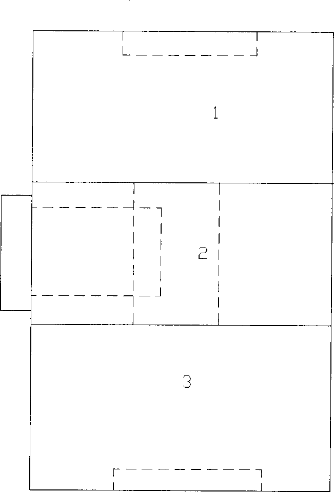
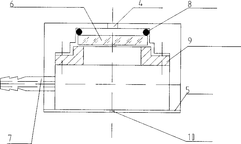
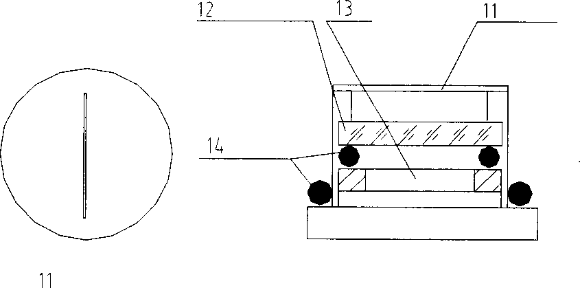
[0028] like Figure 1-4 Shown, the present invention is connected by upper, middle and lower three sections. An aperture aperture 4,5 is respectively arranged on the top and bottom of the upper section 1, a spherical laser mirror 6 is arranged in the middle, the center of curvature is at the center of the middle section 2, and an air nozzle 7 is arranged on the side. The inside of the middle section 2 is a cylindrical hole, which is ground into a cylindrical mirror surface, or electroplated to form a mirror surface after fine milling. A side hole is opened on the front side of the middle section 2, and a hollow cylinder is embedded in the side hole. The cylinder goes deep into one end of the middle section. A thin disc 11 with a slit is pasted, and an interference filter 12 that blocks the laser itself and its Rayleigh scattering is installed behind the thin disc 11, and the filter 12 closes the slit. The lower section 3 is also provided with an aperture aperture 15,16 up and...


PUM

PropertyMeasurementUnit
Sensitivityaaaaaaaaaa

Abstract

A laser Raman sample cell consists of top section including eyelet light diaphragm set at top and bottom separately, spherical total reflector, curvature center at center of middle section and air tap at side; middle section including columnar hole at internal, a side hole with hollow cylinder in it, thin round plate with an interference filter at back and bottom section including eyelet light diaphragm set on top and bottom separately, convergent lens at middle and focal point at center of middle section.

Description

technical field [0001] The invention relates to a gas sample cell, in particular to a laser Raman sample cell for gas analysis. The invention belongs to the technical field of trace gas detection. Background technique [0002] Raman technology has been widely used in atmospheric monitoring and gas analysis of products in industrial production and combustion processes. Its sensitivity has reached 1ppm. However, the traditional and improved Raman sample cells in recent years are independent of the Raman spectrometer. The Raman scattered light generated in the sample cell must pass through the external optical system to be efficiently coupled into the slit of the spectrometer. Such instruments and equipment are loose in structure, large in size, sensitive to vibration and background light, difficult to use and adjust, and can only be installed in a darkroom with an optical shock-absorbing platform. [0003] Found through literature search to prior art, U.S. Patent No.: 4676...

Claims


Application Information

Patent Timeline
Patent Type & Authority Applications(China)
IPC IPC(8): G01N21/01G01N21/65
Inventor 高成岳黄鞠铭杨虎夏宇兴
Owner 上海众毅工业控制技术有限公司
Why Eureka
Try Eureka