Camera and focus detection device

A focus detection and camera technology, applied in the direction of cameras, focusing devices, installation, etc., can solve the problems of increased cost, increased memory capacity, large-scale processing circuit in the camera, etc., achieves high-precision focus offset correction, and simplifies the correction method. Effect

Inactive Publication Date: 2005-07-27
OLYMPUS CORP
View PDF3 Cites 8 Cited by
  • Summary
  • Abstract
  • Description
  • Claims
  • Application Information

AI Technical Summary

Problems solved by technology

[0007] However, the device described in Patent Document 2 performs complex calculations based on chromatic aberration correction data of a specific wavelength relative to a reference wavelength and the main color of the subject light measured by a colorimetric un

Method used


Image

  • Camera and focus detection device
  • Camera and focus detection device
  • Camera and focus detection device

Examples


Example

[0055] (First embodiment)

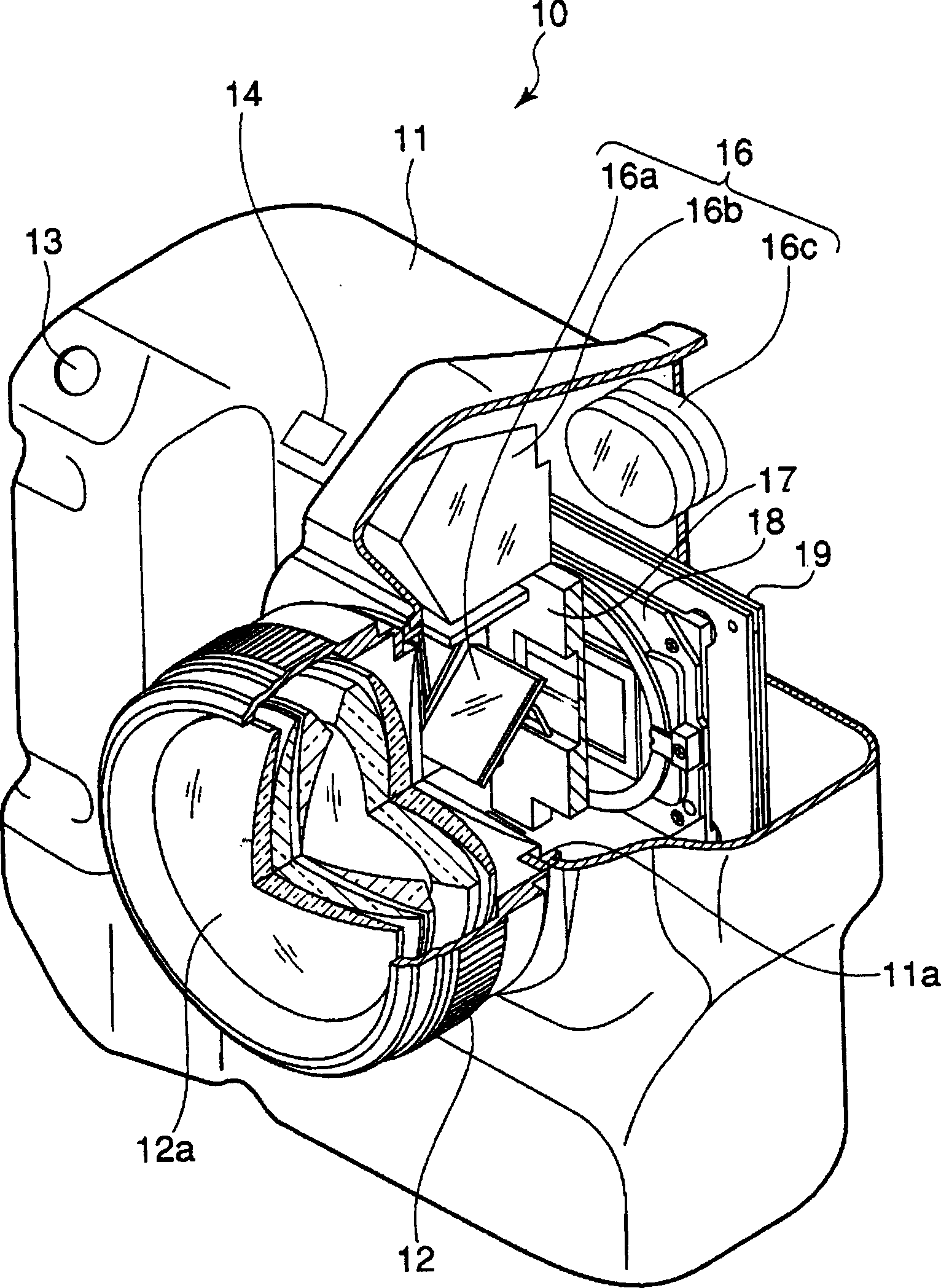
[0056] figure 2 It is a perspective view of the digital camera according to the first embodiment of the present invention in a cutaway and schematically showing its internal structure.

[0057] in figure 2 In this embodiment, the digital camera 10 includes a camera body 11 and a lens barrel 12 that are independently configured, and the camera body 11 and the lens barrel 12 have a structure that can be freely attached to and detached from each other.

[0058] The above-mentioned lens barrel 12 adopts a structure in which a photographing optical system 12a composed of a plurality of photographing lenses and a driving mechanism thereof is held inside. The photographing optical system 12a is composed of, for example, a plurality of optical lenses and the like, and transmits the light beam from the subject to form a subject image formed by the subject light beam at a predetermined position (the image sensor 40 described later) On the photoelectric convers...

Example

[0204] (Second embodiment)

[0205] Next, the second embodiment of the present invention will be described.

[0206] In the first embodiment described above, the case where any one of the light source types is selected is taken as an example. However, in reality, when photographing by a window in a fluorescent lamp room, there are many photographing situations where there are multiple light sources. The second embodiment described below adopts a structure that can obtain an appropriate exposure amount even when a plurality of light sources are mixed.

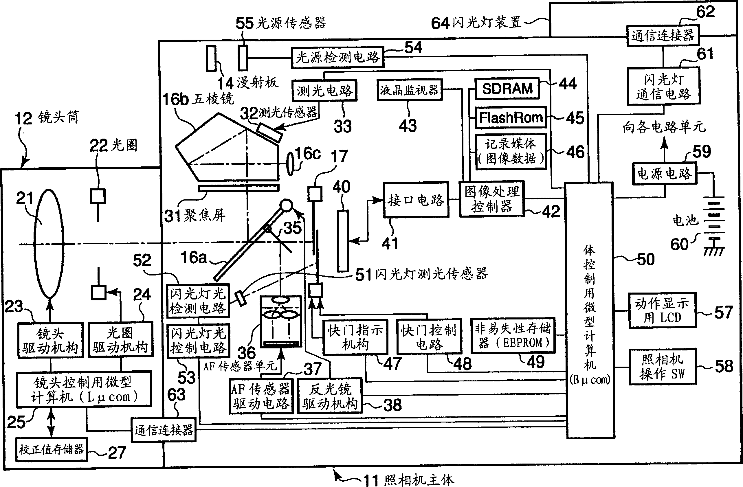
[0207] In addition, this second embodiment is different from the above-mentioned first embodiment only in the control operation. The structure and basic operation of the camera are basically different from those in the first embodiment. Figure 1 to Figure 14 The shown is the same, so the same parts are given the same reference numbers, and their illustrations and descriptions are omitted.
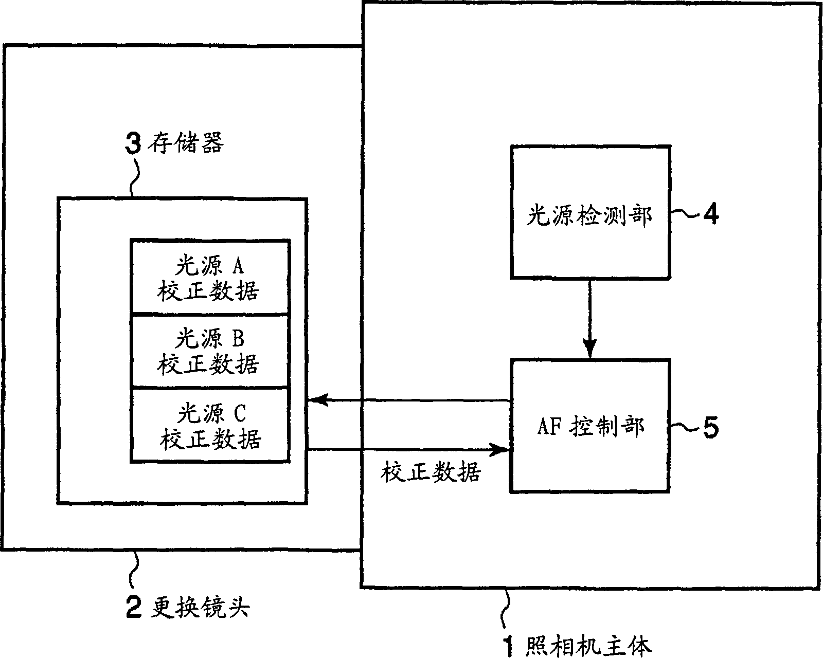
[0208] First, refer to Figure 16 The calc...

Example

[0237] (Third Embodiment)

[0238] Next, a third embodiment of the present invention will be described.

[0239] The third embodiment is an example in which correction of the subject distance is added.

[0240] It is well known that the amount of focus shift produced by the light source varies with the position of the focusing lens. It is also well known that the position of the focusing lens, that is, the amount of extension of the focusing lens, causes the change in spherical aberration (refer to Figure 19 ).


PUM


Abstract

The object of the invention is to reduce the cost of an interchangeable lense, camera or the like by simplifying a correction method thereby downsizing a memory and a processing circuit, and to provide the camera and a focus detecting device which can correct the out of focusing highly precisely. When a light source illuminating a subject is detected by a light source detection part 4 in a camera body 1, a signal corresponding to the light source is outputted from the light source detection part 4. In addition, a correction value for correcting defocus according to the type of the light source, which is stored in a memory 3, is read as correction data. Based upon the signal from the light source detection part 4 and the correction data read from the memory 3, an AF control part 5 performs the focus detection.

Description

technical field [0001] The present invention relates to a camera and a focus detection device, and more particularly to a focus detection device for a camera that corrects the focus point position based on a light source incident on the photographic lens in order to reduce the influence of chromatic aberration of the photographic lens or the like. Background technique [0002] Conventionally, a technology has been developed to detect the brightness of the subject and the background light during shooting, and to perform correction at the time of distance measurement. For example, the so-called Phase Difference AF (Automatic Adjustment AF) that detects the focus state of the measurement object from the positional relationship of a pair of images formed on a pair of light-receiving element rows, and performs focus adjustment of the photographing lens based on the detection result. Focus) automatic focus adjustment device (for example, refer to Patent Document 1). [0003] In s...

Claims


Application Information

Patent Timeline
IPC IPC(8): G03B13/36G02B7/28G02B17/02
Inventor 井出昌孝
Owner OLYMPUS CORP
Why Eureka
Try Eureka