Object detection device, object detection server, and object detection method

A technology of object detection and object detection, which is applied in the direction of measuring devices, instruments, time registers, etc., can solve problems such as dynamic range limitation, difficult requirements, and difficult application

Inactive Publication Date: 2005-07-27
PANASONIC CORP
View PDF1 Cites 10 Cited by
  • Summary
  • Abstract
  • Description
  • Claims
  • Application Information

AI Technical Summary

Problems solved by technology

[0006] However, the previous technology is very difficult for such requirements
That is to say, in the above technology, as the transmitter approaches, only the camera that shoots the detection object can be selected, but detailed information such as where the detection object is and what posture it takes in the captured image cannot be obtained.
In addition, because the antenna is used to specify the position, there will be a relatively large error (several meters to more than ten meters) in the position information, that is, when there are other people near the detection object, it is difficult to identify two people in the image
[0007] In the past, several techniques for detecting objects from camera images using only image processing have been known, but most of them can only be used under very strictly limited conditions, and false detections may occur in the environment of people's daily life many, it is difficult to apply
The reasons for this are the limitations of the dynamic range of the camera itself, the existence of various objects and backgrounds other than the detection target, and changes in sunlight and lighting. kind of change etc.
[0008] The human visual mechanism can make use of a large amount of knowledge and rules acquired based on experience, and can perform correct detection even in a changing environment. However, it is still very difficult at this stage to make the device and the human obtain the same knowledge and rules. of
In addition, for such processing, a large amount of processing capacity and memory are required, which brings about problems such as an increase in processing time and cost.

Method used


Image

  • Object detection device, object detection server, and object detection method
  • Object detection device, object detection server, and object detection method
  • Object detection device, object detection server, and object detection method

Examples


no. 1 Embodiment approach

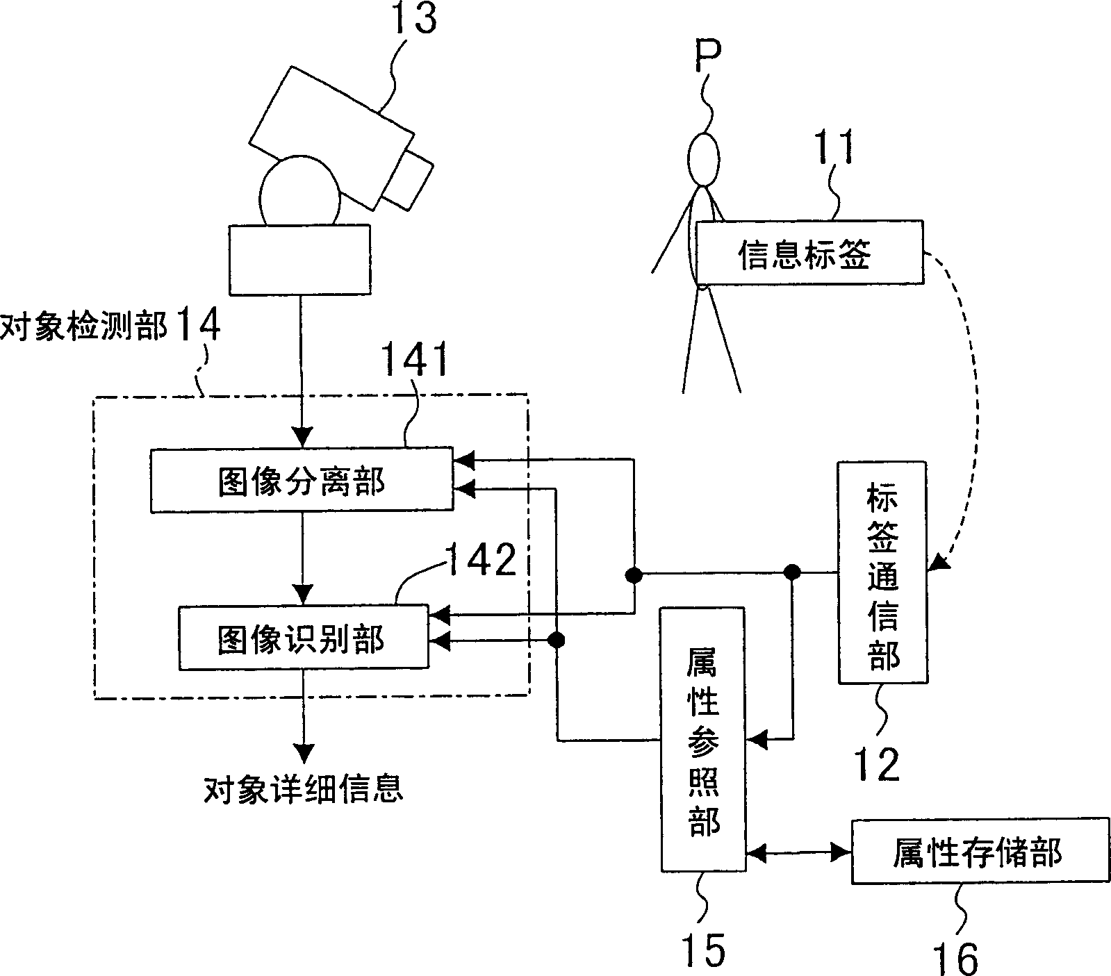
[0049] figure 1 It is a block diagram showing a configuration example of the object detection device according to the first embodiment of the present invention. exist figure 1 In the composition of , person P is taken as a given detection object. exist figure 1 Among them, 12 is a tag communication unit that receives the tag information sent by the information tag 11 attached to the person P, 13 is an imaging unit that captures an image, and 14 is using the tag information received by the tag communication unit 12 to capture images captured by the imaging unit 13. The object detection unit that detects the person P in the image. The imaging unit 13 is installed at a position where an image including a person P can be captured.

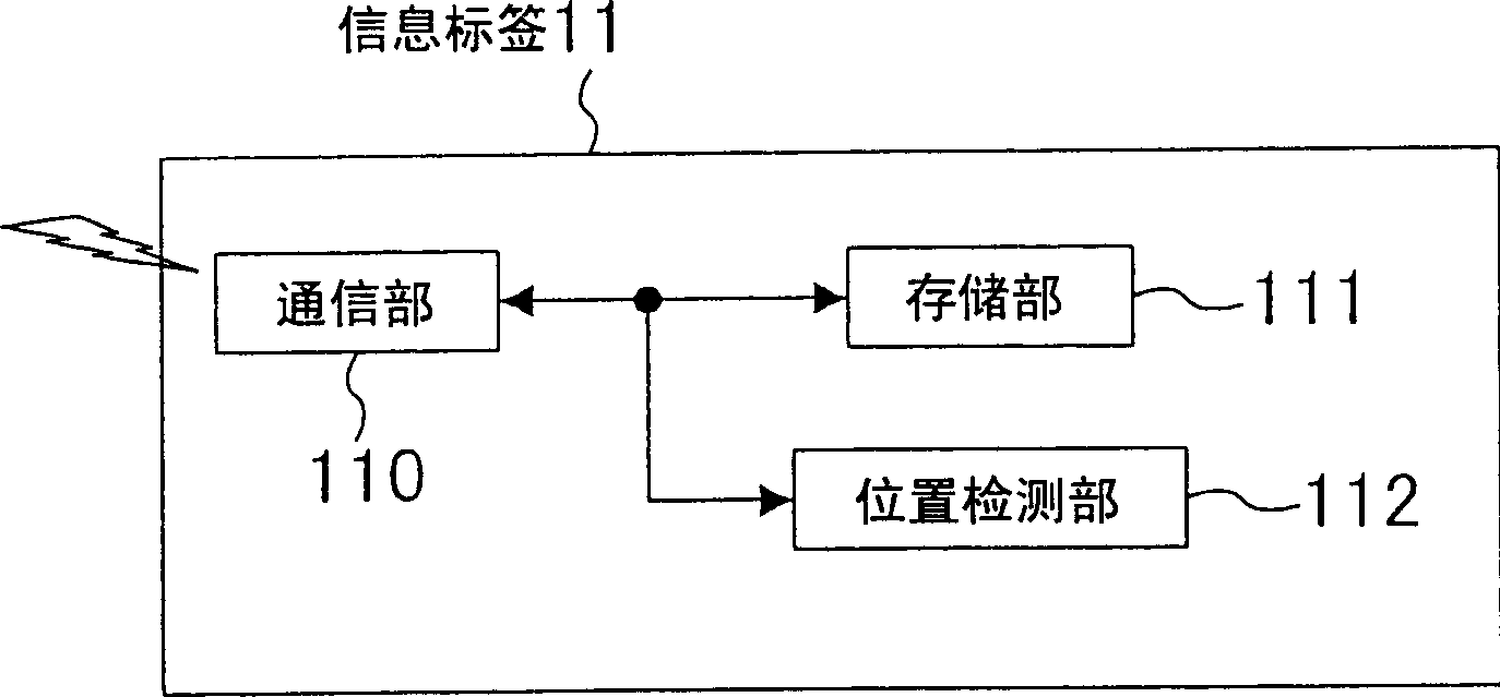
[0050] figure 2 It is a conceptual block diagram showing the internal configuration of the information tag 11 . exist figure 2 Among them, the communication unit 110 communicates with the tag communication unit 12 in a non-contact manner throu...

no. 2 Embodiment approach

[0102] In the second embodiment of the present invention, an object is detected using a mobile robot having a camera as a predetermined detection target.

[0103] Figure 15 It is a figure which shows the situation of this embodiment. Figure 15 In , a mobile robot 40 is placed on the ground FL in the home. The robot 40 as an object detection device includes: the camera 13 serving as an imaging unit; the tag communication unit 12 described in the first embodiment; the object detection unit 14 and the attribute reference unit 15 . In addition, the attribute storage unit 16 is installed in a place different from the robot 40 , and the attribute reference unit 15 refers to the attribute information stored in the attribute storage unit 16 through wireless communication.

[0104] On the floor FL, there are a horizontal cylindrical object Oa and a spherical object Ob. Objects Oa and Ob are both red. Information tags 11 are incorporated in the objects Oa and Ob, respectively, and I...

no. 3 Embodiment approach

[0116] In the third embodiment of the present invention, a person serving as a subject is detected as a given detection target by a portable video camera. The portable cameras mentioned here include portable movie cameras and digital cameras, handheld phones with cameras, and information terminals.

[0117] Figure 20 It is a situation figure which shows this embodiment. exist Figure 20 In this example, the person Pd is photographed outdoors by the portable video camera 50 equipped with the imaging unit 13 . The person Pd has an information tag 11 that transmits ID information that specifies the person Pd as tag information using ultrasonic waves. Generally, when using the ultrasonic transmitter used for measuring the distance, it can detect the range of about 20m from the camera. Of course, the detection range changes according to the intensity of the ultrasonic waves.

[0118] The camera 50 includes: two microphones 51a, 51b; a tag communication unit 12A, and an object...


PUM


Abstract

Provided is a object detection device. A tag communication section (12) receives tag information transmitted from an information tag (11) attached to a person (P) to be detected. An attribute lookup section (15) looks up an attribute storage section (16) using ID included in the tag information to obtain attribute information such as the height of the person (P). A target detection section (14) specifies the position, posture and the like of the person (P) in an image obtained from an imaging section (13) using the attribute information.

Description

technical field [0001] The present invention relates to a technique for detecting the correct position, posture, etc. of a given detection object such as a person or an object from an image. Background technique [0002] Patent Document 1 describes a technique for controlling the orientation and zoom of a surveillance camera as a transmitter approaches. Specifically, a radio wave transmitter that transmits an ID code is attached to a person to be monitored, and an antenna that detects the proximity of the transmitter is installed in an area where entry is prohibited. When the antenna detects that the transmitter approaches, multiple surveillance cameras In this method, a surveillance camera near the position where the antenna can be photographed is automatically selected, and the image of the selected camera is displayed on the surveillance monitor. In addition, the ID code possessed by the transmitter is read through the antenna, and the height of the person corresponding ...

Claims


Application Information

Patent Timeline
Patent Type & Authority Applications(China)
IPC IPC(8): G01S11/14G06K9/00G06T7/00G07C9/00H04N7/18
CPCG01S11/14G06K9/00362H04N7/183G07C9/00G06T7/0044G06T7/74G06V40/10
Inventor 今川太郎中川雅通吾妻健夫冈本修作
Owner PANASONIC CORP
Why Eureka
Try Eureka