Micro-consumption intelligent solar lamp for lawn

A technology of solar energy and solar cells, applied in the field of solar lamps and lanterns, can solve problems affecting the flux and lighting time of solar lawn lights, and unfavorable promotion and application of solar lawn lights

Inactive Publication Date: 2005-08-10
陈其芳
View PDF1 Cites 2 Cited by
  • Summary
  • Abstract
  • Description
  • Claims
  • Application Information

AI Technical Summary

Problems solved by technology

Therefore, the waste of so much electric energy will seriously affect the luminous flux and lighting time of solar lawn lights.
This is not conducive to the promotion and application of solar lawn lights

Method used


Image

  • Micro-consumption intelligent solar lamp for lawn
  • Micro-consumption intelligent solar lamp for lawn

Examples


Embodiment Construction

[0009] The present invention will be described below in conjunction with the embodiments and the accompanying drawings.

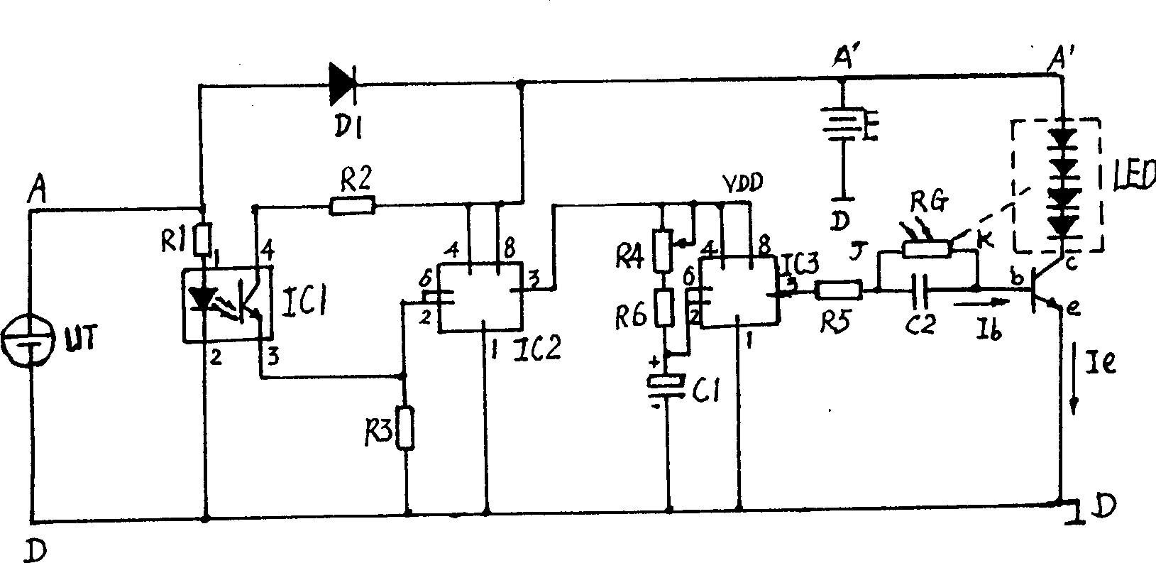
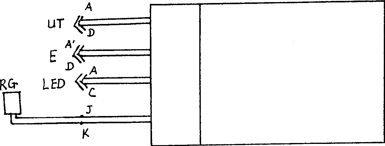
[0010] See figure 1 with figure 2 , A low-consumption smart solar lawn lamp, comprising a solar battery UT, a battery E, a light-emitting diode LED as a light source, and a controller. The controller is equipped with a control circuit on the circuit board. The control circuit has an optocoupler IC1. Pin 1 and pin 2 of the optocoupler IC1 are connected to the two ends of the solar cell UT.

[0011] See figure 1 , Pin 3 of optocoupler IC1 is connected to pin 2 and pin 6 of time base integrated circuit IC2. Time base integrated circuit IC2 is used. When pin 3 (output end) of optocoupler IC1 is at high level, time base integrated circuit IC2 outputs a light-on signal; when pin 3 (output end) of optocoupler IC1 is at low level, time base integrated Circuit IC2 outputs a light-off signal. The time-base integrated circuit IC2 has the advantages of strong driving abi...


PUM


Abstract

The disclosed light fitting includes solar battery, accumulator, light emitting diode, and controller. The controller sets up control circuit including an optical couple element on circuit board. First pin and second pin of the said optical couple element are connected to two ends of the solar battery respectively. At evening, voltage of the solar battery becomes lower from higher, and output resistance value of the optical couple element becomes larger from smaller; at morning, voltage of the solar battery becomes higher from lower, and output resistance value of the optical couple element becomes smaller from larger. Variety of output resistance magnitude of optical couple element is adopted to distinguish day and night without lighting window so as to simplify circuit and reduce no load loss greatly.

Description

1. Technical field [0001] The invention relates to a solar lamp, in particular to a solar lawn lamp. 2. Background technology [0002] Solar lawn lights are widely used because of their compliance with environmental protection requirements and their superior safety performance, and their demand will become greater and greater. Unlike the lawn lights powered by city electricity, solar lawn lights can be controlled centrally, but must be controlled separately. A Chinese patent once disclosed "a solar lawn lamp control circuit" (ZL032207204, CN2612203Y, announcement date: April 14, 2004). The boost circuit in the control circuit is an L and C oscillating boost circuit, and the inductor L In order to close the magnetic circuit inductance coil; in the control circuit, the input end of the controller is connected to the solar cell and the storage battery, the output end of the controller is connected to the oscillating booster circuit, and the output of the oscillating b...

Claims


Application Information

Patent Timeline
Patent Type & Authority Applications(China)
IPC IPC(8): H05B37/02
CPCY02B20/48Y02B20/40
Inventor 陈其芳陈建炳陈德先
Owner 陈其芳
Why Eureka
Try Eureka