

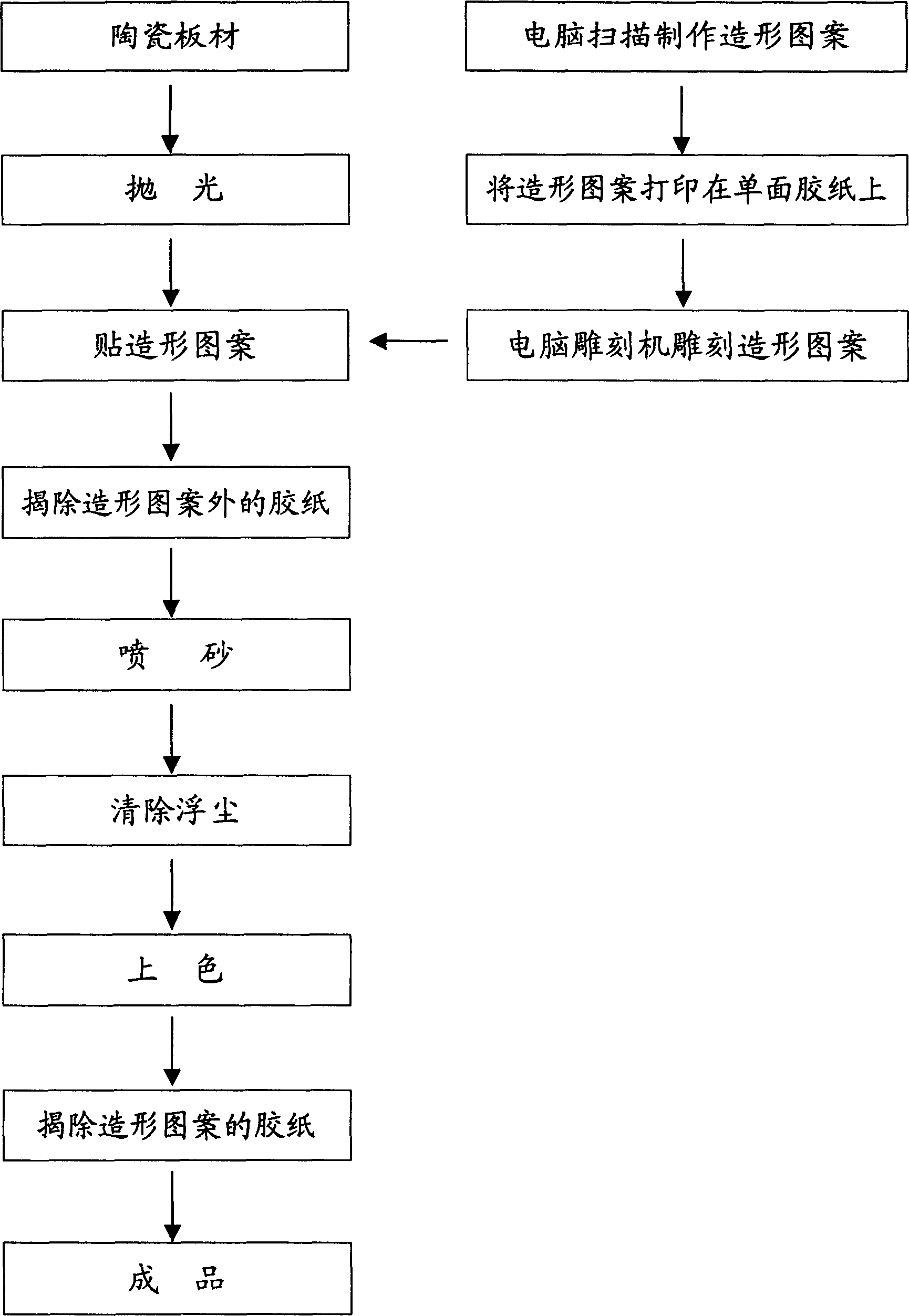
Method for fabricating patterns on ceramic veneer in sand-blasting modus
A technology for ceramic plates and patterns is applied in the field of ceramic building materials, making patterns on ceramic plates, and building materials. Effect
- Summary
- Abstract
- Description
- Claims
- Application Information
AI Technical Summary
Problems solved by technology
Method used
Image

Examples
specific Embodiment approach 2
[0047] The second embodiment is the first unit test under the premise of the basic test. Carry out on the basis of specific embodiment one, just in the specific implementation process, selected stone plate, metal plate, plastic plate respectively for use; Also selected the ceramic plate of matte matte surface that is not polished for use in addition. Both obtained the expected good effect.
specific Embodiment approach 3
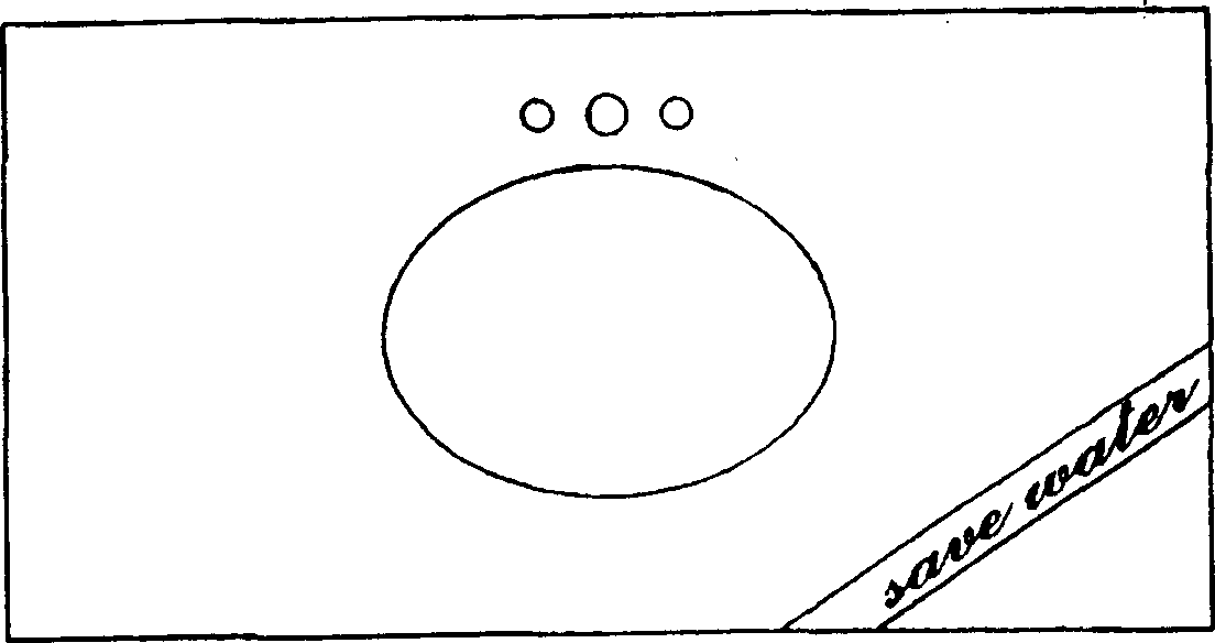
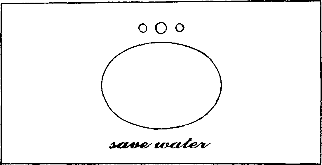
[0048] The third embodiment is the second unit test under the premise of the basic test. Carry out on the basis of specific embodiment 1, only shape pattern is respectively the shape pattern of foreign language character figure, the shape pattern of flower figure, the shape pattern of plant figure, the shape pattern of animal figure, the shape pattern of bird figure, fish The modeling pattern of figure, the modeling pattern of insect figure, the modeling pattern of object figure, the modeling pattern of geometrical figure, the modeling pattern of picture figure are carried out. Both obtained the expected good effect.
specific Embodiment approach 4
[0049] The fourth embodiment of the present invention is the third unit test under the premise of the basic test. Carried out on the basis of the specific embodiment one, but the single-sided adhesive tape pasted on the ceramic plate is implemented with two layers and three layers respectively; , and the method of pasting the stainless steel sheet with the shape pattern made in advance was implemented; in addition, instead of pasting the single-sided adhesive tape of the shape pattern on the ceramic plate, the glue of the shape pattern is directly sprayed on the ceramic plate by spraying glue. layer is implemented. Both obtained the expected good effect.
PUM
| Property | Measurement | Unit |
|---|---|---|
| Thickness | aaaaa | aaaaa |
| Depth | aaaaa | aaaaa |
| Hardness | aaaaa | aaaaa |
Abstract
Description
Claims
Application Information