Cooling jacket for electric machines

A technology for cooling enclosures and cooling covers, which is applied in the direction of cooling/ventilation devices, casings/covers/supports, electromechanical devices, etc., and can solve problems such as cost and heat transfer efficiency.

Inactive Publication Date: 2005-08-17
EMERSON ELECTRIC CO
View PDF1 Cites 32 Cited by
  • Summary
  • Abstract
  • Description
  • Claims
  • Application Information

AI Technical Summary

Problems solved by technology

Although the cooling enclosure described in this patent is generally satisfactory, the flow channel configuration used in this design is not optimal for cost and heat transfer efficiency

Method used


Image

  • Cooling jacket for electric machines
  • Cooling jacket for electric machines
  • Cooling jacket for electric machines

Examples


Embodiment Construction

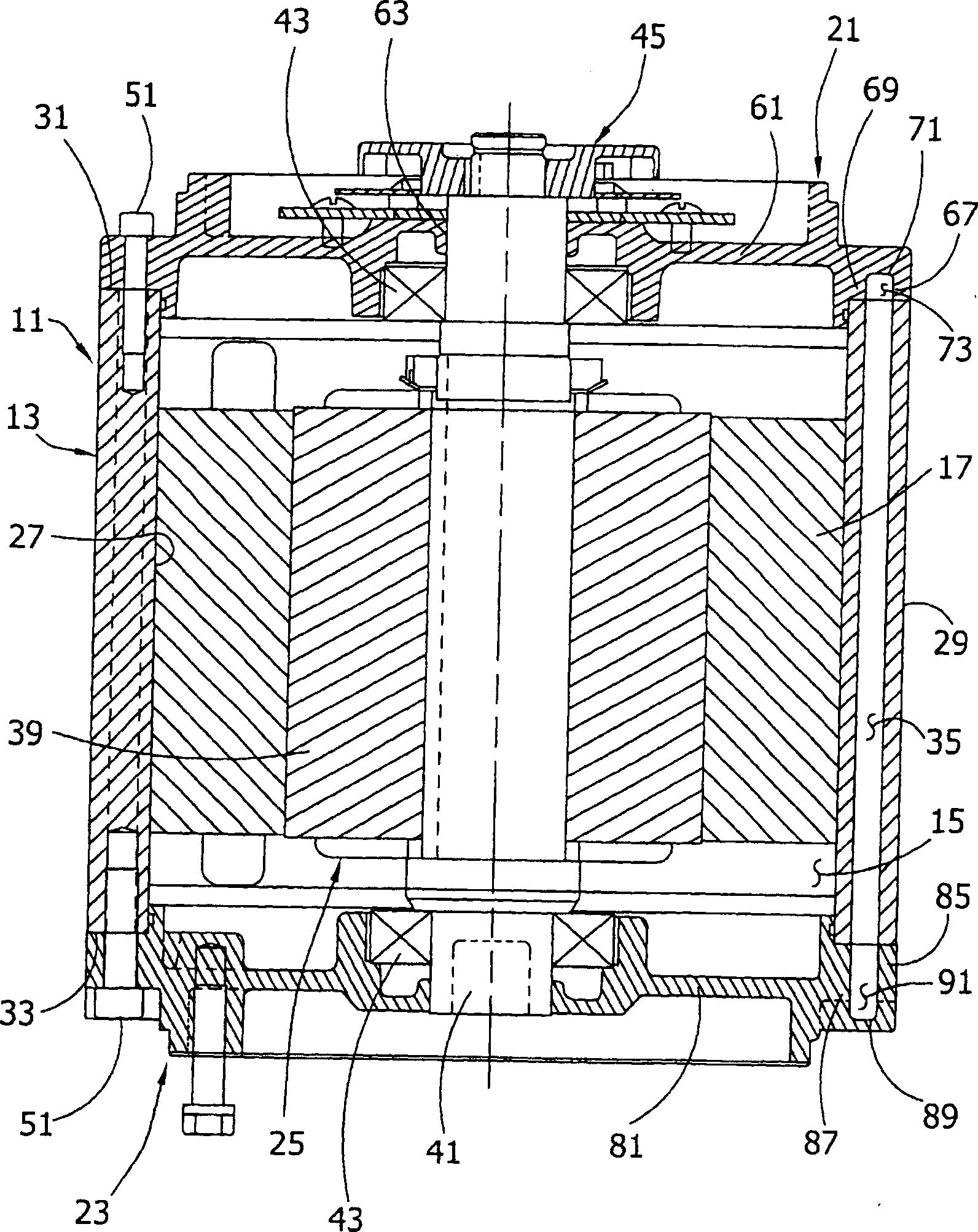
[0023] Referring now to the accompanying drawings in particular figure 1 , a cooling enclosure of the present invention is indicated by reference numeral 11 as a whole. The casing includes a casing body portion 13 defining a cavity 15 for receiving a stator 17 of an electric motor, and first and second body portions generally indicated by 21 and 23 respectively and connected to opposite ends of the body portion. end cap. (The term "motor" as used herein refers to a machine that works as an electric motor or generator.) As an example, the cooling enclosure 11 may be used to cool an electric motor of an electric vehicle, where heat transfer efficiency and weight are important factors. A conventional rotor and shaft assembly, indicated generally at 25 , is rotatable within stator 17 .

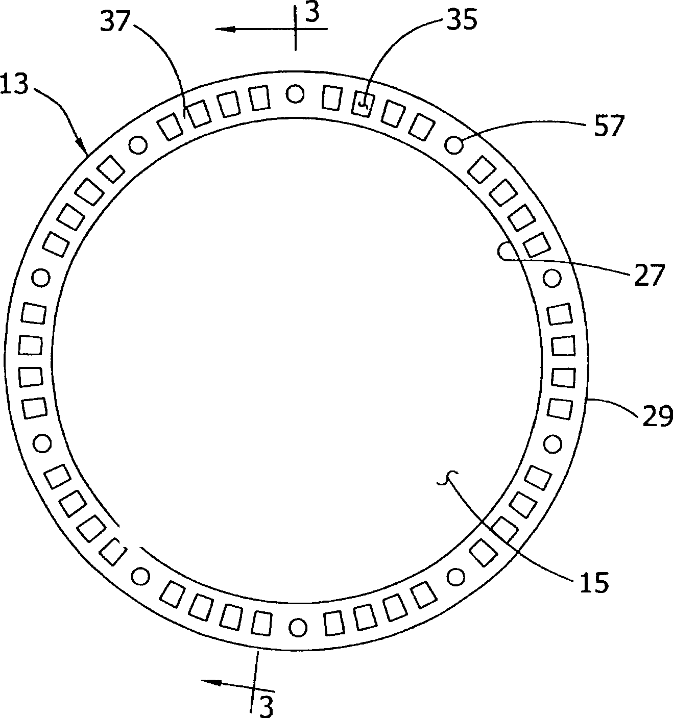
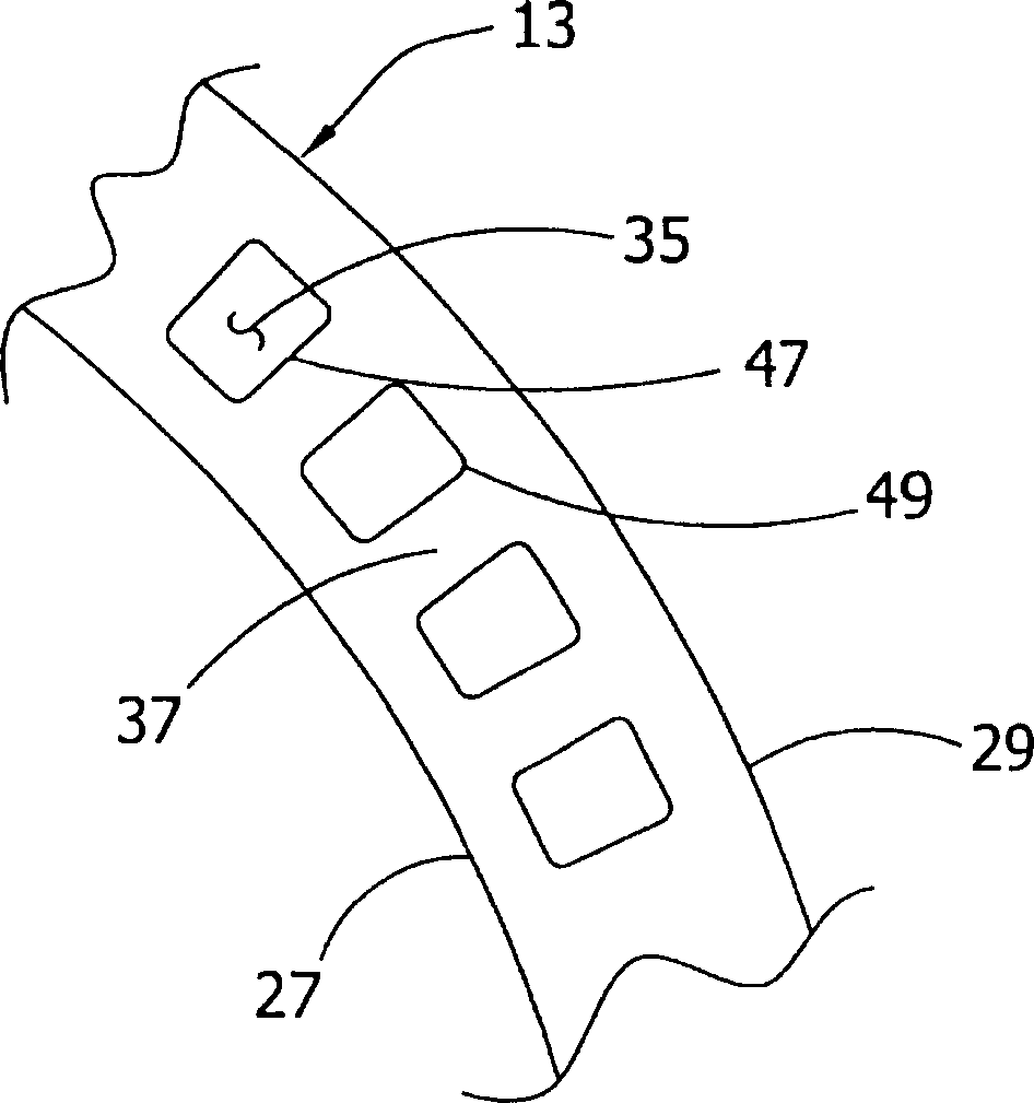
[0024] refer to figure 1 To 3, the housing body portion 13 is made of a thermally conductive material and has coaxial inner and outer surfaces 27, 29, and annular end faces 31 and 33 at opposit...


PUM


Abstract

A cooling jacket for cooling the stator of an electric machine. The jacket includes a cooling jacket body having a cylindric inner surface defining a cavity for receiving the stator of a motor, axial flow passages in the body for the flow of a coolant, and end caps connected to opposite ends of the body. Coolant flows through an inlet in one of the end caps and is directed through the flow passages along at least one serpentine path to an outlet. Each flow passage has a cross sectional shape defined entirely by three or more substantially linear sides.

Description

technical field [0001] The present invention relates generally to systems for cooling electric motors / electric machines, and in particular to a cooling enclosure for cooling electric motors and / or generators with high heat dissipation requirements. Background technique [0002] This invention is in the same technical field as US Patent No. 6,300,693, entitled "Motor Cooling Housing Assembly and Method of Manufacture," assigned to Emerson Electric Co., which is incorporated herein by reference. The '693 patent discloses a cooling shroud with axial passages through which coolant flows to cool an electric machine (motor or generator) such as a brushless permanent motor operating at high speed and driven by a fuel-powered turbine to generate electrical power. The stator of the magnetic motor. Although the cooling enclosure described in this patent is generally satisfactory, the flow channel configuration used in this design is not optimal for cost and heat transfer efficiency. ...

Claims


Application Information

Patent Timeline
Patent Type & Authority Applications(China)
IPC IPC(8): H02K5/20H02K9/19
CPCH02K5/20H02K9/19H02K5/203H02K2205/09H02K5/04H02K2213/03
Inventor P·K·博斯特威克
Owner EMERSON ELECTRIC CO
Why Eureka
Try Eureka