Middle high density hydraulic pulper

A hydraulic pulper and pulper technology, applied in the field of papermaking machinery, can solve the problems of increased power consumption, easy cutting of fibers, and increased production costs, and achieve the effects of reducing power consumption, improving quality, and avoiding friction

Inactive Publication Date: 2005-08-24
李风宁
View PDF0 Cites 19 Cited by
  • Summary
  • Abstract
  • Description
  • Claims
  • Application Information

AI Technical Summary

Problems solved by technology

[0003] The bottom of the tank of the existing hydropulper is flat, and the bottom of the rotor of the hydropulper is equipped with a bottom knife. There is a strong mechanical friction between the rotor and the bottom of the tank, and this strong mechanical friction will easily cut t

Method used


Image

  • Middle high density hydraulic pulper
  • Middle high density hydraulic pulper

Examples


Example Embodiment

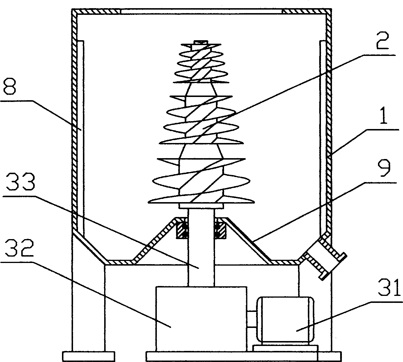
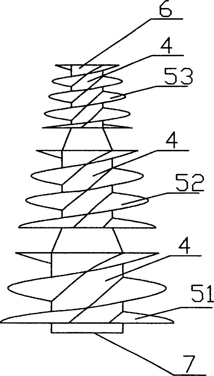
[0012] Such as figure 1 As shown, the medium and high-concentration hydraulic pulper includes a pulper tank 1. The bottom of the tank 1 is vertically installed with a pulper rotor 2 provided with spiral blades. The driving end of the pulper rotor 2 is connected to the tank body 1. The lower driving device is fixedly connected. The bottom of the trough 1 corresponding to the driving end of the pulper rotor 2 is an upward convex boss 9 which is a frustum, of course it can also be a cylinder. Shaped or streamlined protrusions, this structural shape is convenient to make the vortex circulation of the slurry in the tank smooth and unimpeded, avoiding the friction between the rotor and the tank; due to the setting of the boss, the bottom of the tank is formed An annular groove is conducive to the collection of non-fibrous impurities; the inner wall of the pulper tank 1 is provided with a number of defibrating fiber protrusions 8. This structure can increase the number of collisions and...


PUM


Abstract

The invention discloses a hydraulic pulp kneader, including the trough solid whose bottom has pulp kneader with corkscrew leaf set vertically, the driving end of pulp kneader is connected to the driving device below the trough solid, and the bottom of trough solid of the pulp kneader driving end is saddlebacked, making the leaf of pulp kneader get away from the bottom of trough solid, avoiding friction between the trough solid and pulp kneader completely, decides the route of whole vorticity circulation and local vorticity circulation formed in the trough solid is lengthed, so that the times of collision is increased and the waste paper is scattered to be the single fiber and it won't be cut off, also, all kinds of nonfiber mixture are kept wholly, it has decreased the energy cost and increased the quality of paper pulp.

Description

technical field [0001] The invention belongs to the field of papermaking machinery, and in particular relates to a medium-high consistency hydraulic pulper. Background technique [0002] There are three principles for the shredding of various waste papers: one is to completely eliminate fiber bundles; the other is not to cut or cut fibers as little as possible; the third is not to destroy or damage various non-fibrous impurities as little as possible. [0003] The bottom of the tank of the existing hydropulper is flat, and the bottom of the rotor of the hydropulper is equipped with a bottom knife. There is a strong mechanical friction between the rotor and the bottom of the tank, and this strong mechanical friction will easily cut the fiber for a while. , reducing the quality of pulp; second, it will destroy various non-fibrous impurities, which will cause difficulties for the subsequent impurity removal process; third, it will cause a substantial increase in power consumpti...

Claims


Application Information

Patent Timeline
IPC IPC(8): D21B1/32D21B1/34
CPCY02W30/64
Inventor 李风宁
Owner 李风宁
Why Eureka
Try Eureka