Installation for making a cut, crease and the like having a plate-shaped frame

A technology of equipment and incision, applied in the direction of cutting tools for shearing machines, driving devices for metal rolling mills, metal processing equipment, etc., can solve problems such as difficulty in accessing bottom rolls

Inactive Publication Date: 2005-08-31
吉恩亨利罗伯特马代恩
View PDF2 Cites 14 Cited by
  • Summary
  • Abstract
  • Description
  • Claims
  • Application Information

AI Technical Summary

Problems solved by technology

Another disadvantage is that the rollers must first be assembled with the box before being fastened to the frame
[0004] Another disadvantage of the known device is that the rollers are located one behind the other when viewed in the direction of the groove
The bottom roller is difficult to access, which is a disadvantage in operation

Method used


Image

  • Installation for making a cut, crease and the like having a plate-shaped frame
  • Installation for making a cut, crease and the like having a plate-shaped frame
  • Installation for making a cut, crease and the like having a plate-shaped frame

Examples


Embodiment Construction

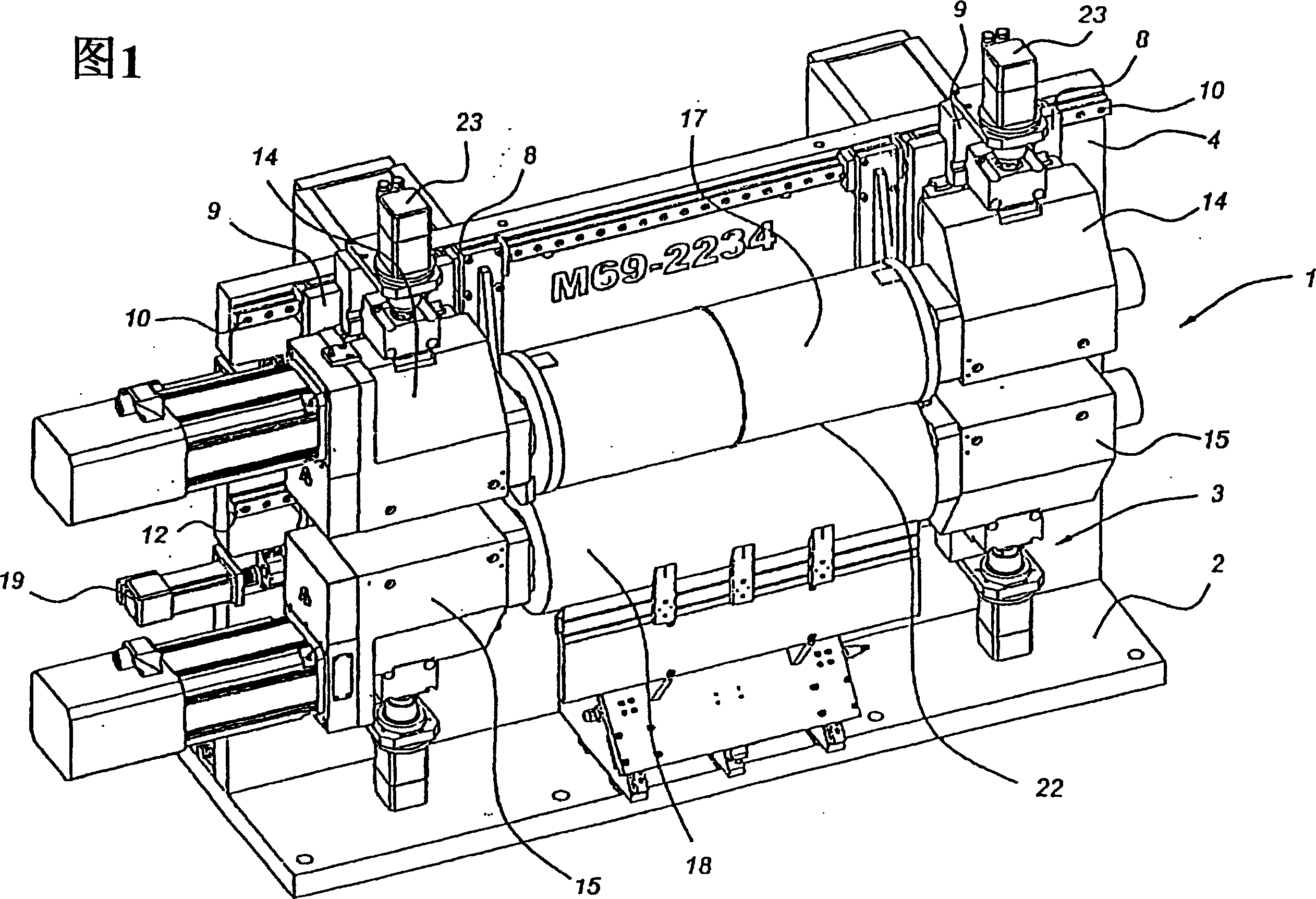
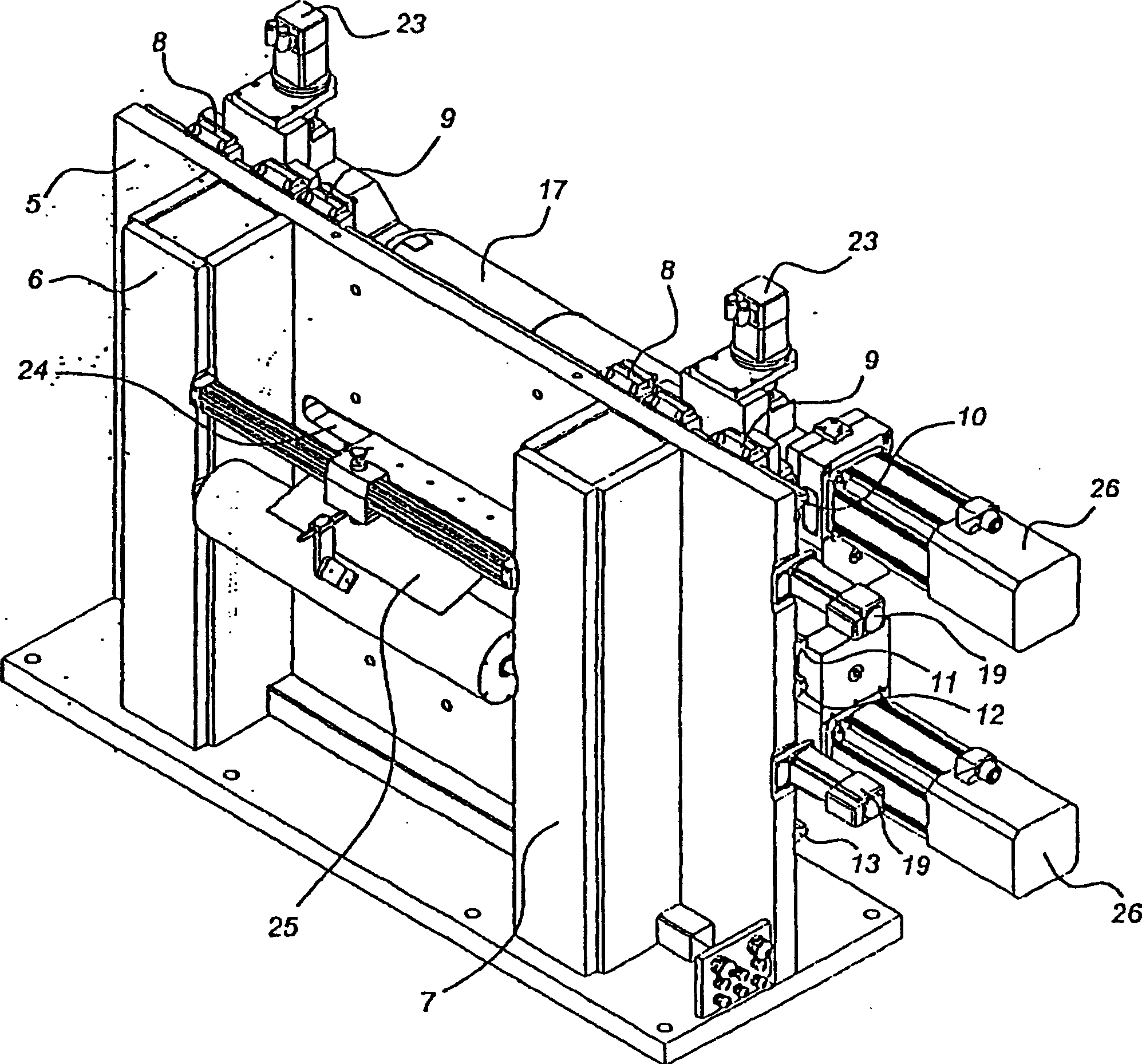
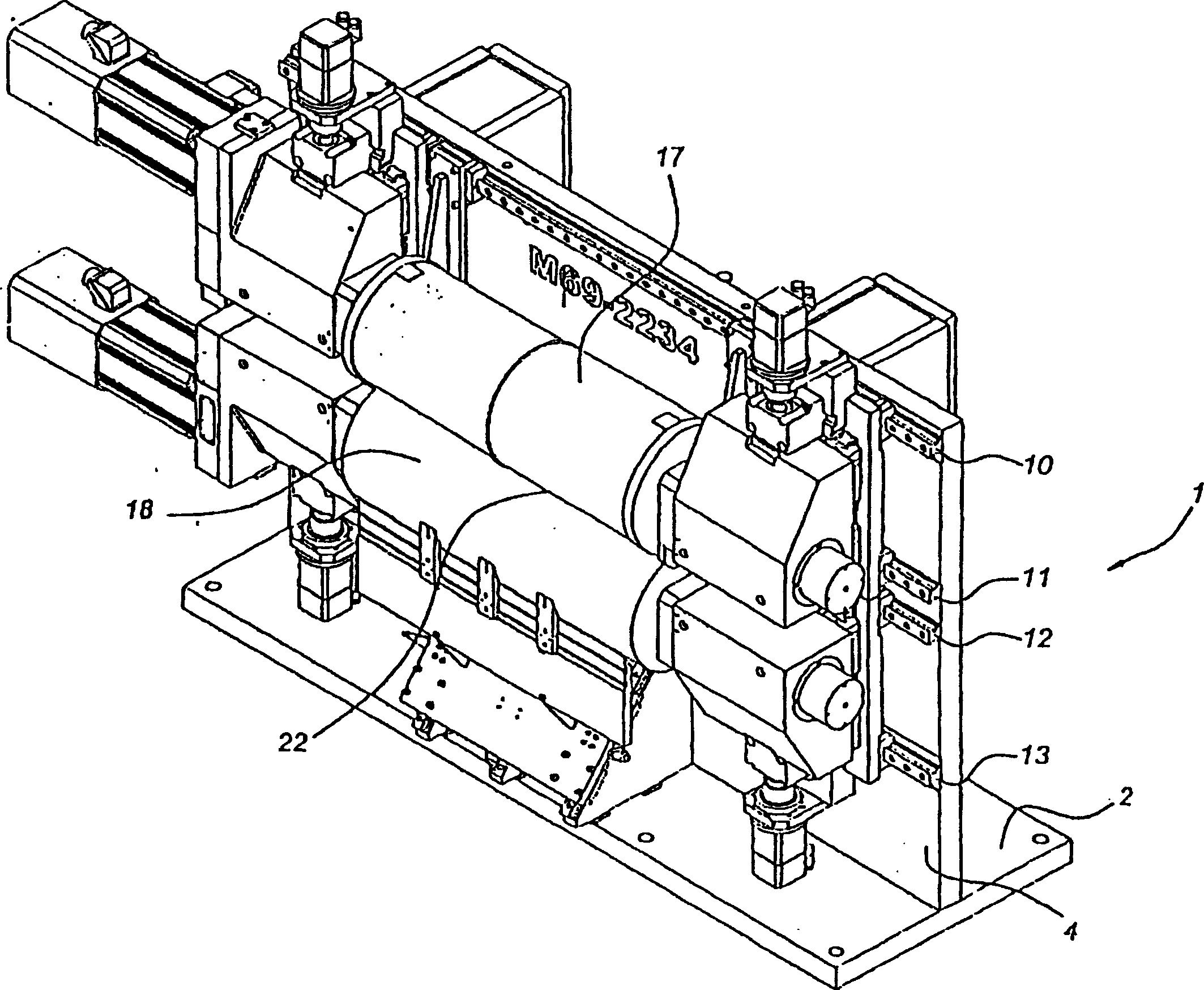
[0031] The rotary device shown in FIGS. 1 to 4 has a frame generally indicated by 1 which mainly includes a base 2 and a plate 3 . Tablet 3 has a flat front 4 and a flat rear 5 . Reinforcing columns 6 , 7 extending to the base 2 are secured to the flat back 5 .

[0032] On the front 4 of the plate 3 are mounted two pairs of vertical rails 8 , 9 . The rails 8, 9 in each pair are connected to each other and are supported on horizontal rails 10-13 so that they can move.

[0033] Two heads 14, 15 are fitted on each pair of vertical rails. A stub shaft 16 is rotatably supported in each head. As can be seen in FIG. 4 , the minor axis 16 has the shape of a frustum of a cone. In each case, the rollers 17 , 18 are supported on two short shafts 16 placed opposite each other, as shown in FIG. 1 .

[0034] With regard to mounting and respectively removing the rollers, the heads 14 , 15 are removed by moving the associated pair of guide rails 8 , 9 apart using linear actuators 19 . R...


PUM


Abstract

A rotary installation comprises a frame, a pair of rollers that define a pinch, mounting means for supporting the rollers on the frame, adjustment means for moving the mounting means and the rollers with respect to the frame as well as drive means for making the rollers rotate. The frame has an essentially flat shape determined by two main faces facing away from one another, on one of which main faces the rollers and mounting means are located.

Description

technical field [0001] The present invention relates to an apparatus for forming cuts, creases or embossments etc. in sheet material such as cardboard, the apparatus comprising a frame, a pair of rollers defining a nip therebetween and roller surfaces, the rollers The surface has a relatively high surface portion and a relatively low surface portion, such as a cutting edge and / or edge for forming a crease in the sheet material as it passes through the nip, and also includes a support for the frame Fixing means for the rollers, adjustment means for moving the fixing means and the rollers relative to the frame and drive means for rotating the rollers. Background technique [0002] Such a device is disclosed in EP-A 610650 . This known device has a U-shaped frame with a horizontal base relative to which the two arms are directed upwards. The arms each have a slot that is open at the top. The rollers are supported in boxes so that they can rotate, and the boxes are housed in ...

Claims


Application Information

Patent Timeline
Patent Type & Authority Applications(China)
IPC IPC(8): B21B13/02B21B31/02B21B31/08B21B35/06B23D35/00B26D7/26B31F1/10B41F13/30
CPCB41P2213/734B41P2213/804B21B13/02B21B2031/026Y10T83/483B21B31/02B26D7/265B31F1/10B21B2031/023Y10T83/4833B21B31/08B23D35/008B41F13/30B21B35/06B26D7/2621
Inventor 吉恩·亨利·罗伯特·马代恩
Owner 吉恩亨利罗伯特马代恩
Why Eureka
Try Eureka