

Method for preparing hydrogen rich gas through reforming plasma and equipment
A technology of plasma and plasma, which is applied in the field of hydrogen-rich gas reformulation by ion mass reformation, can solve the problems of low power utilization efficiency, difficulty in large-scale production, harsh reaction conditions, etc., and achieves the effects of wide application, mild reaction conditions and simple equipment structure
- Summary
- Abstract
- Description
- Claims
- Application Information
AI Technical Summary
Problems solved by technology
Method used
Image

Examples
Embodiment 1
[0024] Example 1: Preparation of hydrogen-rich gas by submerged glow plasma
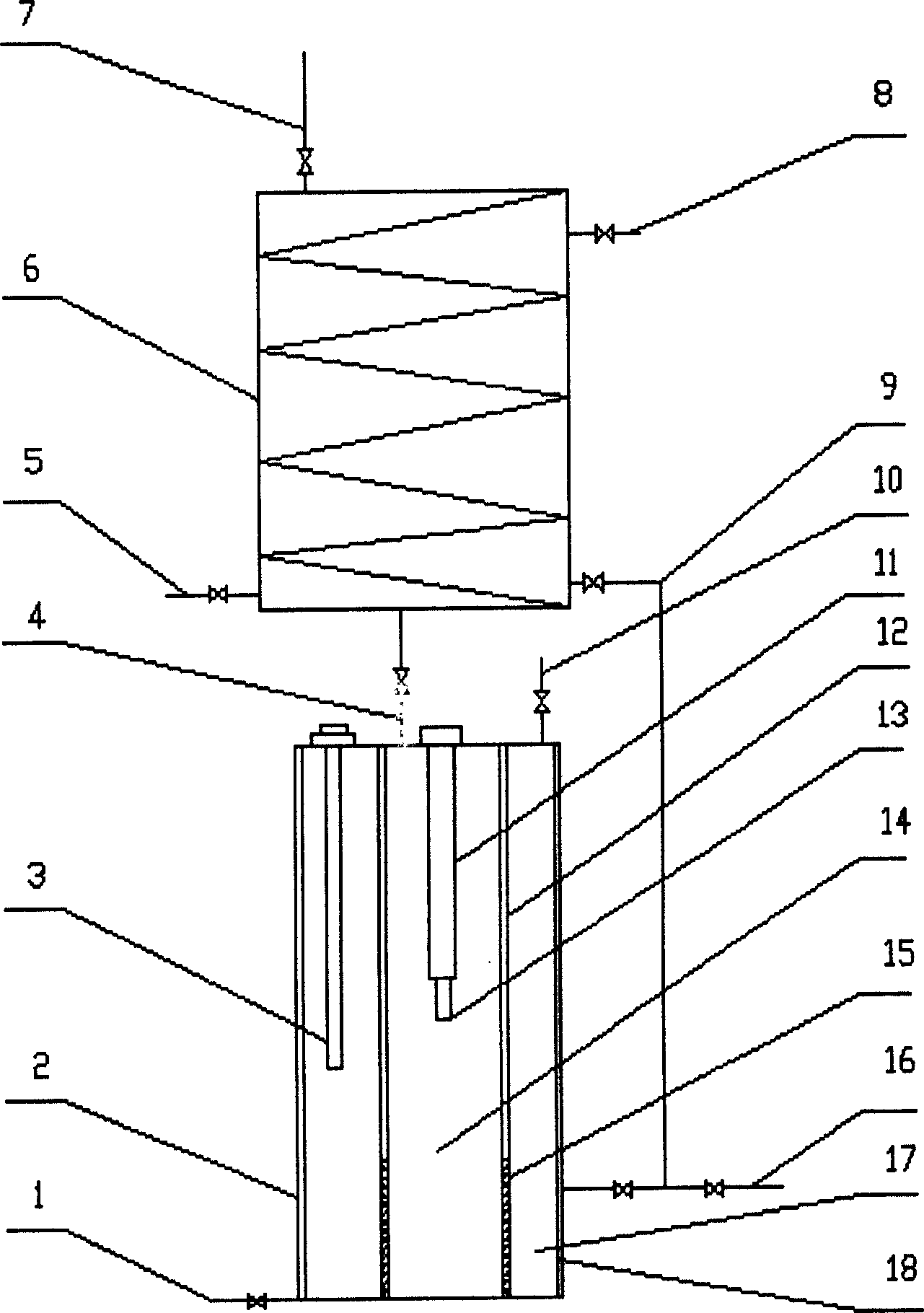
[0025] as attached figure 1 The shown device, a device for realizing a method for preparing hydrogen-rich gas by plasma reforming is composed of a plasma reformer 2 and a condenser 6, and the plasma reformer 2 is composed of a cathode 3, a cathode sleeve 11, an anode 13, The two-pole separator 12, the two-pole diaphragm 15, the condenser 6, and the condensate return pipe 9 are composed; their connection relationship and relative positions are as follows: the plasma reformer 2 is a cylindrical container, and the two-pole separator 12 and the two-pole diaphragm 15 are ring-shaped , respectively installed on the top and bottom of the plasma reformer 2, and mutually docked, the plasma reformer is divided into two parts, the anode chamber 17 and the cathode chamber 14; the cathode chamber 14 is located in the middle, and the anode chamber 17 is located at the periphery; the anode chamber 17 The inner wal...
Embodiment 2
[0031] Example 2: Preparation of hydrogen-rich gas by submerged glow plasma
[0032] as attached figure 1 As shown, a device for preparing hydrogen-rich gas by plasma reforming is composed of a plasma reformer 2 and a condenser 6. The plasma reformer 2 is rod-shaped except for the anode, the cathode material is tungsten-cerium alloy, and the cathode and anode electrodes are The ratio of the electrode area is adjusted to 1:1.25, and the two-pole separator material is insulating ceramics, and other structures and connections are the same as in Example 1.
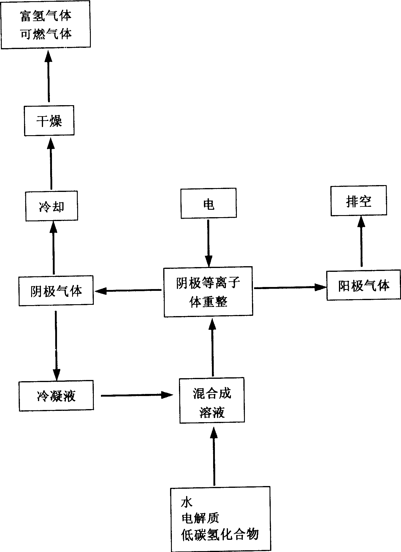
[0033] According to the process route figure 2 The process steps and conditions shown are as follows:
[0034] Step 1: Mix methanol and water into a solution at a volume ratio of 1:1, and add electrolyte sodium hydroxide to the solution to adjust the conductivity of the solution to 0.05S.m -1 ;
[0035] Step 2: Place the prepared solution in the reformer containing the cathode and anode electrodes, so that the cathode and a...
Embodiment 3
[0037] Example 3: Preparation of hydrogen-rich gas by submerged glow plasma
[0038] as attached figure 1 As shown, a device for preparing hydrogen-rich gas by plasma reforming is composed of a plasma reformer 2 and a condenser 6. The plasma reformer 2 is rod-shaped except for the anode, and the ratio of the electrode areas of the cathode and anode electrodes is adjusted to 1:5, except that the material of the two pole separators is insulating ceramics, the other structures and connections are the same as in Example 1.
[0039] According to the process route figure 2 The process steps and conditions shown are as follows:
[0040] Step 1: Mix ethanol and water into a solution at a volume ratio of 1:0.15, and add electrolyte sodium carbonate to the solution to adjust the conductivity of the solution to 1.4S.m -1 ;
[0041] Step 2: Place the prepared solution in the reformer containing the cathode and anode electrodes, so that the cathode and anode electrodes are both below ...
PUM
 Abstract
Description
Claims
Application Information