Injector screw axial pulse displacement method and apparatus

An axial displacement, injection machine technology, applied in the field of the axial pulsation displacement of the screw of the injection machine, can solve the problems of inconvenient adjustment of vibration force and poor adjustment effect, etc.

Inactive Publication Date: 2005-09-07
SOUTH CHINA UNIV OF TECH
View PDF2 Cites 16 Cited by
  • Summary
  • Abstract
  • Description
  • Claims
  • Application Information

AI Technical Summary

Problems solved by technology

Adjust the vibration amplitude, generally by adjusting the vibration force of the vibration, but it is inconvenient to adjust the vibration force of the two, and the effect of the adjustment is not good.

Method used


Image

  • Injector screw axial pulse displacement method and apparatus
  • Injector screw axial pulse displacement method and apparatus
  • Injector screw axial pulse displacement method and apparatus

Examples


Embodiment 1

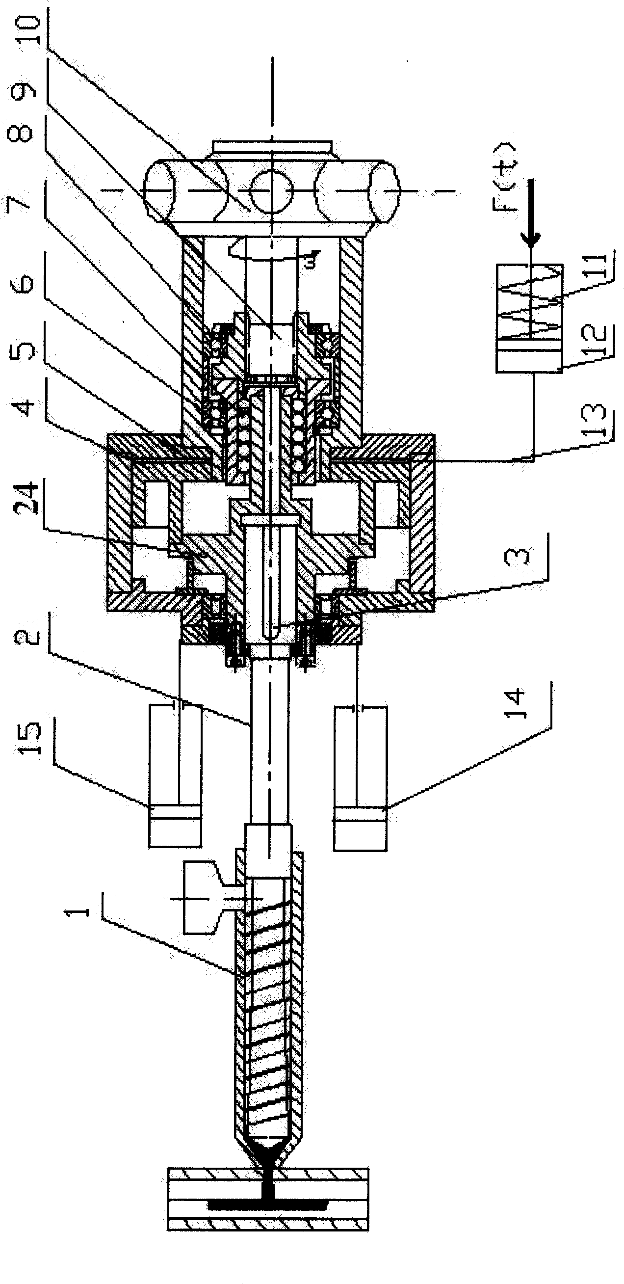
[0015] Such as figure 1 As shown, the screw axial pulsation displacement device of the injection machine is a structure in which the piston of the vibration cylinder does not rotate. The front end of the piston shaft 24 of the excitation cylinder 5 fixed on the hydraulic motor base is connected with the power transmission shaft 2 of the injection screw 1 through the key 3 and is positioned mutually in the axial direction; The spline 7 is connected with the output shaft 9 of the hydraulic motor 10 , and the rolling spline 7 is supported by positioning bearings 6 and 8 . Rotation drives the rolling spline 7 connected to the output shaft 9 of the hydraulic motor 10, so that the injection screw 1 can either rotate or simultaneously or independently perform axial displacement. The piston 4 of the vibration cylinder is supported axially and radially by the tapered roller self-aligning bearing 17, positioned and installed on the piston shaft 24 of the vibration cylinder through the ...

Embodiment 2

[0025] Such as figure 2As shown, it is the structural form of the vibration cylinder piston rotation. The front end of the piston shaft 24 of the excitation cylinder 5 fixed on the hydraulic motor base is connected with the power transmission shaft 2 of the injection screw 1 through the key 3 and is positioned mutually in the axial direction; The spline 7 is connected with the output shaft 9 of the hydraulic motor 10 , and the rolling spline 7 is supported by positioning bearings 6 and 8 . Rotation drives the rolling spline 7 connected to the output shaft 9 of the hydraulic motor 10, so that the injection screw 1 can either rotate or simultaneously or independently perform axial displacement. The vibration excitation cylinder piston 4 is not independently supported by bearings, and is fixedly connected with the vibration excitation cylinder piston shaft 24, so that the vibration excitation cylinder piston shaft 24 and the vibration excitation cylinder piston 4 can axially vi...

Embodiment 3

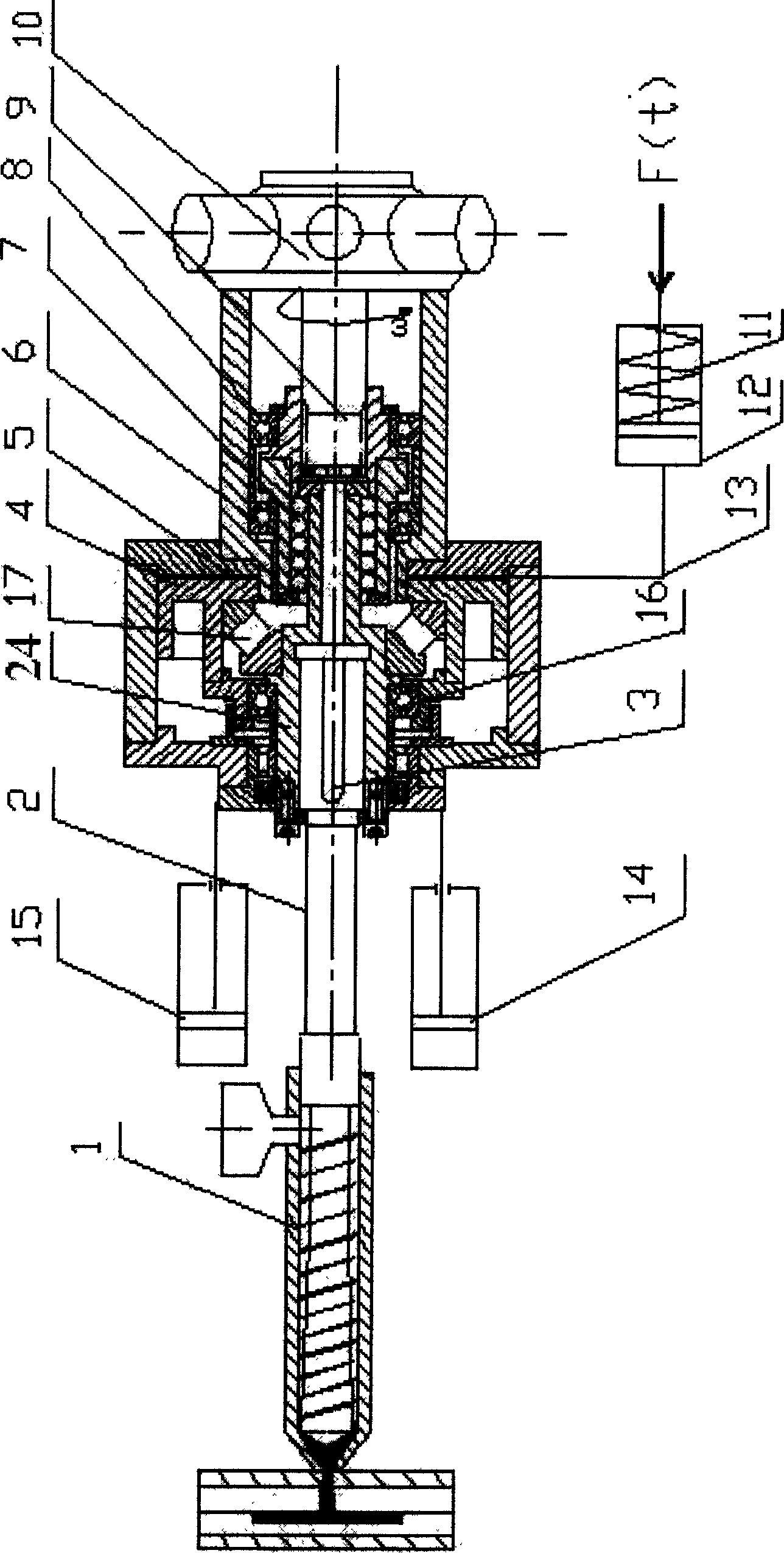
[0029] Such as image 3 The structure shown is a single cylinder direct injection. It includes an excitation oil cylinder 5 fixed on the injection seat and an excitation source oil cylinder 12 that provides axial vibration under the action of an alternating external force F. The axial vibration oil pressure generated by the excitation source cylinder 12 of axial vibration is connected to the injection cylinder 5 through an oil pipe 13 . The power transmission shaft 2 of the injection screw 1 is connected with the piston shaft 24 of the excitation cylinder 5 through the key 3, and the piston shaft 24 is fixedly connected with the piston 4. Thus, the periodic pulsation generated by the exciting oil cylinder acts on the screw 1 through the piston shaft 24 and the power transmission shaft 2, so that the screw 1 can perform periodic axial vibration while axially displacing. After the axial displacement and axial vibration are superimposed Make screw 1 make axial pulsating displac...


PUM


Abstract

The invention relates to the screw rod axial pulsation displacing method and the equipment of a linear polymer injector. It is characterized in that it adopts hydraulic exciting force as the driving power to realize the axial pulsation of the injecting screw rod. Through the exciting oil tank fixed on the hydraulic motor base superpose the pulsation oil pressure produced by exciting oil tank, the injecting pressured produced by the injecting oil tank and the rotary power produced by the hydraulic motor. The axial pulsation displacing of the injecting screw rod can make the melting, the plasitification and the injection processes happen in the periodic vibration state. The invention has the strong points of large exciting output power, simple operation and wide adaptability.

Description

Technical field [0001] The invention relates to a method and a device for the axial pulsation displacement of an injection machine screw. Specifically, it refers to the method of using the hydraulic excitation force as the power of the linear motion mechanism to realize the axial pulsation of the injection screw. Background technique [0002] With the advancement of modern processing technology, vibration technology is more widely used in various fields, and the field of polymer processing is no exception. The plasticizing injection device of the commonly used injection machine is a screw one-line injection device. The injection screw rotates in the circumferential direction. When the material is plasticized, the screw retreats while rotating, and the melted material is sent into the barrel space that the screw head retreats. After reaching a certain amount, the screw is advanced by an external force to act as a plunger to inject the material from the barrel into the cavity...

Claims


Application Information

Patent Timeline
Patent Type & Authority Applications(China)
IPC IPC(8): B29C45/50B29C45/76
Inventor 瞿金平吴宏武
Owner SOUTH CHINA UNIV OF TECH
Why Eureka
Try Eureka