
On-line modularized testing device for optical fiber ring in optic fiber gyroscope

A fiber optic gyroscope and testing device technology, applied in the direction of testing optical performance, etc., can solve the problems of single test, unsatisfactory fiber optic ring, measurement error, etc., and achieve the effects of convenient parameter adjustment, enhanced stability, and enhanced assessment

Inactive Publication Date: 2005-09-07
BEIHANG UNIV
View PDF0 Cites 12 Cited by
  • Summary
  • Abstract
  • Description
  • Claims
  • Application Information

AI Technical Summary

Problems solved by technology

Therefore, at present, there is no complete test system for the test of optical fiber rings, and most of them are general single tests.
As a sensor, the sensitivity accuracy, temperature stability, and vibration and shock resistance of the fiber optic ring must be tested in the actual fiber optic gyroscope, otherwise it cannot meet the needs of the fiber optic ring for use, and it is easy to introduce measurement errors during the test. Therefore, this test There is a big difference between the method and the temperature and vibration and shock resistance requirements of the actual optical fiber ring

Method used


Image

  • On-line modularized testing device for optical fiber ring in optic fiber gyroscope
  • On-line modularized testing device for optical fiber ring in optic fiber gyroscope
  • On-line modularized testing device for optical fiber ring in optic fiber gyroscope

Examples


Embodiment Construction

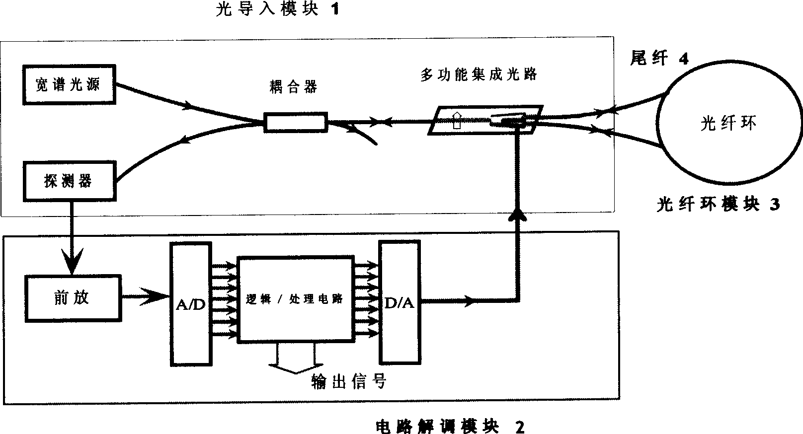
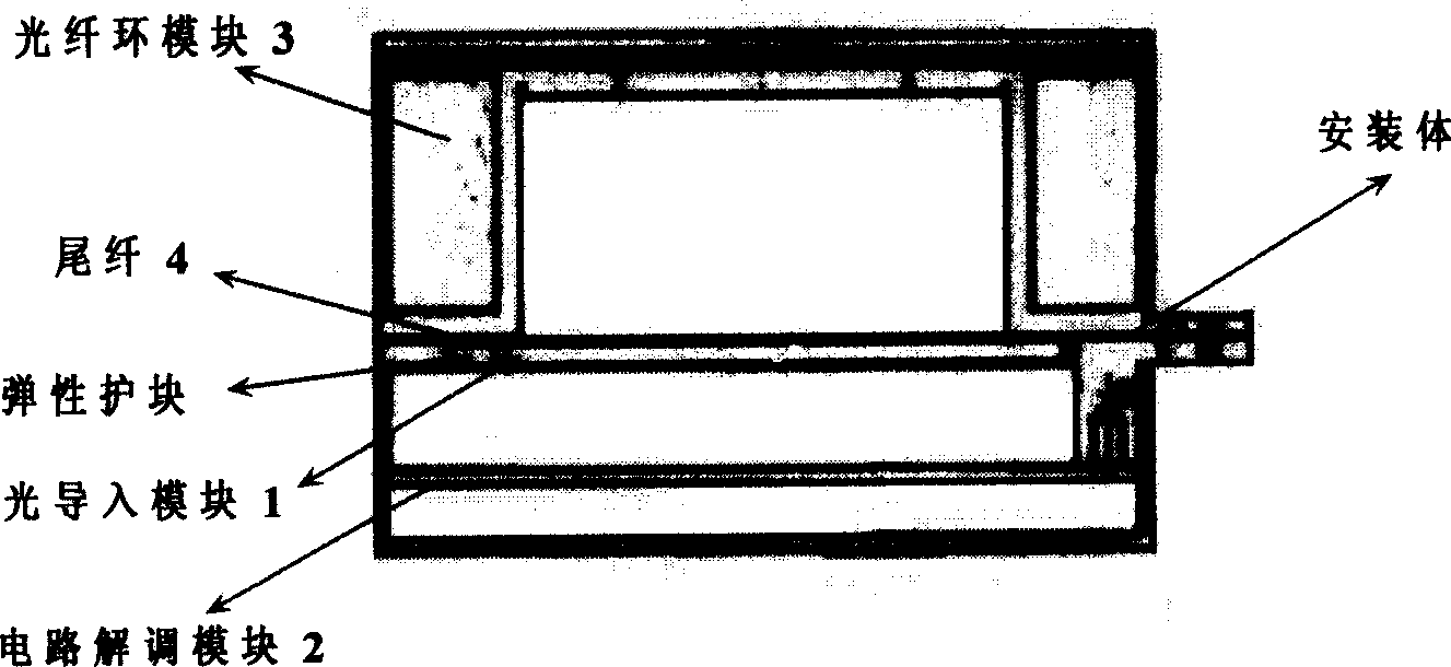
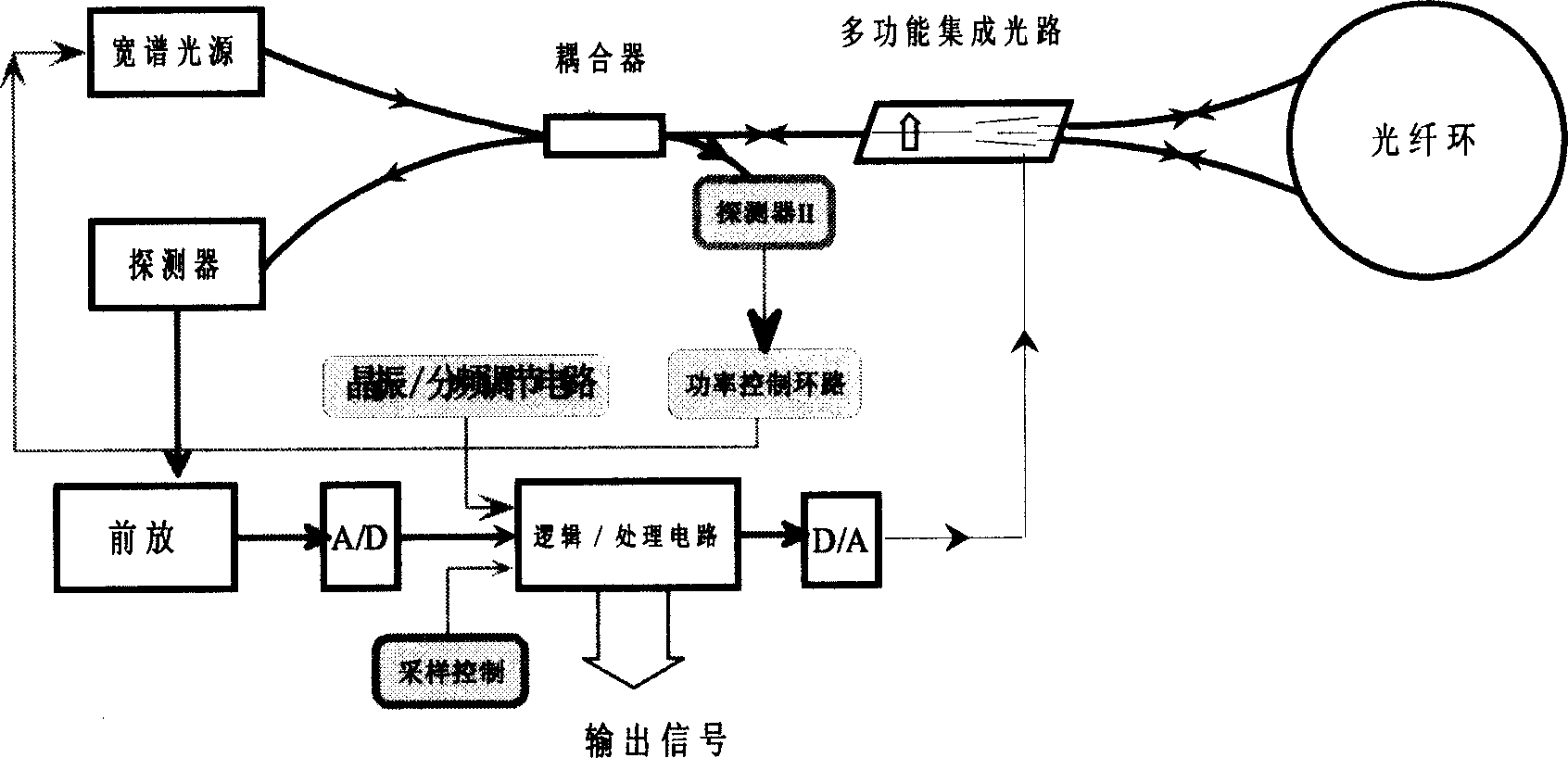
[0011] like figure 1 As shown, the present invention is composed of three modules, a circuit demodulation module 2, an optical import module 1 and an optical fiber ring module 3, and the optical import module 1 provides power and polarization-stabilized coherent light for the optical fiber ring, and then converts the optical interference signal The electrical signal is output to the circuit demodulation module 2; the circuit demodulation module 2 and the light introduction module 1 are connected by a cable to realize signal detection, control and output of the entire optical path; the measured optical fiber ring module 3 and the light introduction module 1 The output is connected through two optical fiber pigtails 4 that have been treated and protected. The optical fiber pigtail 4 is protected by a heat-insulating elastic protective block, and a guide groove is designed in the protective block, so that various arrangements of optical fiber pigtails can be placed in the groove ...


PUM


Abstract

A device for measuring the optical ring of gyroscope on-line modularity, including circuit conciliating modular, light leading-in modular, optical ring modular, the light leading-in modular provides the power and steady polarizing coherent light for the optical ring, transmits the optical interference signal to the electrical signal and exports to the circuit conciliating modular which connected with the light leading-in modular through the electric cable, which can measure, control and output the signal of the whole optical path, the measured optical ring modular is connected with the output end of the light leading-in modular through two pigtail optical fiber being protected, The measurement of the optical ring is in the actual condition of the optical gyroscope and the output and input are identical with the actual use, it not only tests the parameter of the optical ring such as depletion and reciprocity but also tests the system response in the temperature, impact and vibration.

Description

technical field [0001] The invention relates to an online modular testing device for an optical fiber ring in an optical fiber gyroscope. Background technique [0002] Fiber Coil in Fiber Optic Gyroscope (FOG) is a very critical component in interferometric fiber optic gyroscope. The principle of fiber optic gyro is the Sagnac effect in optics. Coherent light transmits in opposite directions in the fiber optic ring. When there is transmission, the two beams of light produce a phase difference, which is detected through light interference, thereby obtaining the angular velocity information of the fiber ring rotation. . The role of the fiber optic ring in the fiber optic gyroscope is: (1) to form a reciprocal optical path for coherent waves to transmit in opposite directions; (2) to generate and amplify the non-reciprocal optical phase difference due to the Sagnac effect; (3) to suppress the optical path in the optical path Various nonreciprocal errors. The device is the se...

Claims


Application Information

Patent Timeline
Patent Type & Authority Applications(China)
IPC IPC(8): G01M11/02
Inventor 肖文伊小素宋凝芳
Owner BEIHANG UNIV
Learn More