Annular standing wave linear ultrasonic motor oscillator

A linear ultrasonic motor, vibrator technology, applied in the direction of generator/motor, piezoelectric effect/electrostrictive or magnetostrictive motor, electrical components, etc., can solve the problems of high manufacturing cost, complex structure, inconvenient design, etc. Achieve the effect of low manufacturing cost, simple driving circuit and easy design

Inactive Publication Date: 2005-09-07
LIAONING UNIVERSITY OF TECHNOLOGY
View PDF0 Cites 41 Cited by
  • Summary
  • Abstract
  • Description
  • Claims
  • Application Information

AI Technical Summary

Problems solved by technology

[0008] The technical problem to be solved by the present invention is to overcome the problems of different order or different types of two-mode operation, complex structure, inconvenient design, and high manufacturing cost of the existing standing wave linear ultrasonic motor vibrator, and to provide a vibrator using the same order Ring standing wave linear ultrasonic motor vibrator with simple structure, easy design, and low manufacturing cost.

Method used


Image

  • Annular standing wave linear ultrasonic motor oscillator
  • Annular standing wave linear ultrasonic motor oscillator
  • Annular standing wave linear ultrasonic motor oscillator

Examples


Embodiment 1

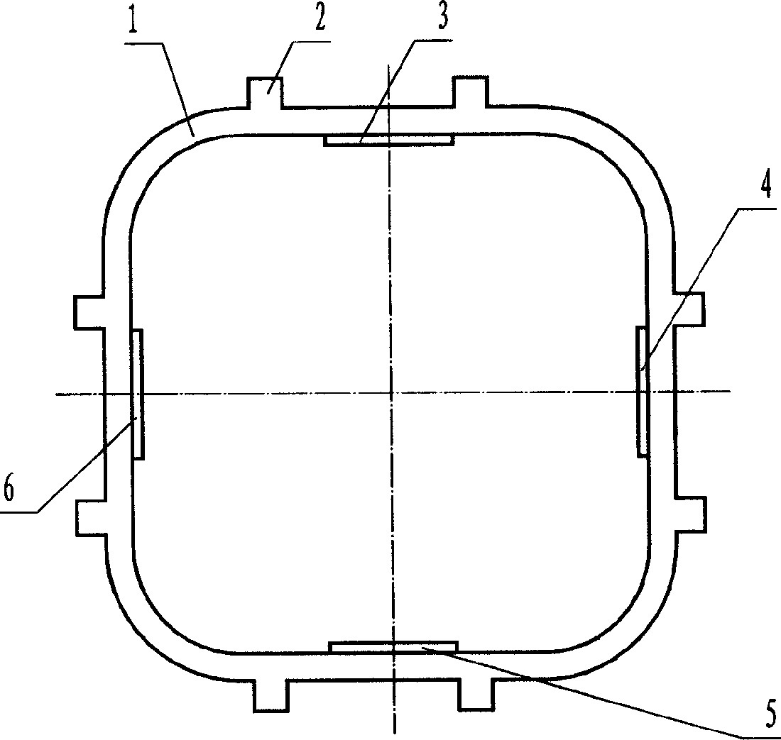
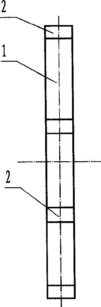
[0034] Such as figure 1 with figure 2 As shown, the present invention is made of metal elastic body 1 and piezoelectric ceramic sheets 3, 4, 5, 6, and several oscillator teeth 2 are arranged on metal elastic body 1, and described metal elastic body 1 is made of four straight beams The square ring formed by one section and four circular arc sections is closed, and the straight beam section is connected by circular arc transition, and the two in-plane bending vibration modes of the same order and frequency or approximately the same frequency of the ring oscillator are used to work; the pressure The electric ceramic sheets 3, 4, 5, and 6 are 4 pieces or a multiple of 4, and the piezoelectric ceramic sheets 3, 4, 5, and 6 are pasted on the inner side of the straight beam section of the square annular metal elastomer 1, and the piezoelectric ceramic sheets 3, 4 , 5, and 6 are divided into two groups, piezoelectric ceramic sheets 3 and 5 form a group, and piezoelectric ceramic sh...

Embodiment 2

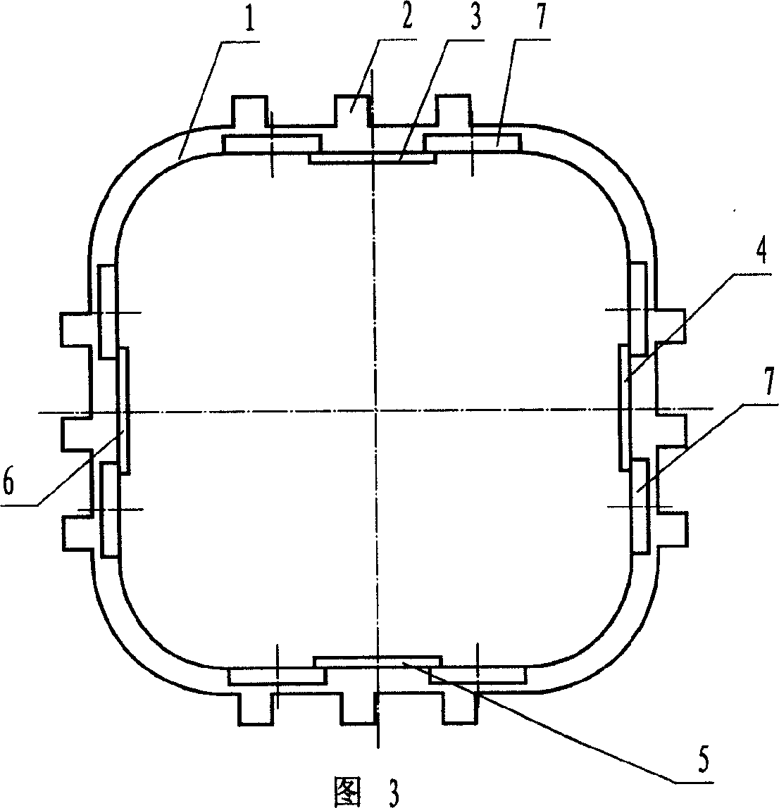
[0037] Figure 3 and Figure 4 As shown, its structure is as in Embodiment 1, the difference is that three vibrator teeth 2 are provided in each straight beam section, and multiple vibrator teeth 2 can also be provided in each straight beam section; There are also fixed wings 7 on both sides of the beam section, so as to fix it on the straight beam section. After the vibrator is fixed, it becomes a stator, which is suitable for non-self-propelled ultrasonic motors that drive the movement of the mover.

Embodiment 3

[0039] As shown in Fig. 5 and Fig. 6, the present invention is made of metal elastic body 10 and piezoelectric ceramic sheets 8, 9, and several vibrator teeth 2 are arranged on metal elastic body 10, and described metal elastic body 10 is made of two A long ring formed by a straight beam section and two circular arc sections closed, the straight beam section is connected by a circular arc transition, and two in-plane bending vibration modes of the same order and frequency or approximately the same frequency of the ring oscillator are used to work; the said The piezoelectric ceramic sheets 8 and 9 are 8 pieces or a multiple of 8, and the piezoelectric ceramic sheets 8 and 9 are pasted on the inner side of the straight beam section of the long annular metal elastic body 10, and the piezoelectric ceramic sheets 8 and 9 are divided into two groups, and the piezoelectric ceramic sheets 8 and 9 are divided into two groups, The electric ceramic sheet 8 is a group, and the piezoelectri...


PUM


Abstract

The invention discloses a vibrator of annular standing wave linear ultrasonic motor, solving the problems of different-order or ¿Ctype two-mode operation, complicated structure, uneasy design and high manufacturing cost; the invention is composed of metallic elastomer and piezoelectric ceramic piece, there are several vibrator teeth on the metallic elastomer and it is characterized in that: the said metallic elastomer is a square or long ring in shape, composed by the closing of straight beam segment and arc segment and works in internal-bending vibrating mode of two surfaces with the same order and frequency or the approximately same frequency; its advantages lie in: working by using the same order vibrating type and the same frequency, thus its driving circuit is simple and its manufacturing cost is lower; its structure is simple and easy to design; etc.

Description

technical field [0001] The invention belongs to an ultrasonic frequency piezoelectric drive element, in particular to an annular standing wave linear ultrasonic motor vibrator. Background technique [0002] Ultrasonic motor is a new type of motor that uses the inverse piezoelectric effect of piezoelectric ceramics to make the vibrator vibrate at ultrasonic frequency, and drives the mover through the friction effect between the vibrator and the mover. Compared with the traditional electromagnetic motor, it has the characteristics of simple structure, flexibility, various motion forms, low speed and high torque, not affected by the magnetic field, self-locking when power is off, small inertia, fast response, good control characteristics, and no need for a deceleration device. Ultrasonic motors can be divided into traveling wave ultrasonic motors and standing wave ultrasonic motors according to the difference in vibration wave patterns utilized by ultrasonic motors. [0003] T...

Claims


Application Information

Patent Timeline
Patent Type & Authority Applications(China)
IPC IPC(8): H02N2/04
Inventor 何勍王宏祥
Owner LIAONING UNIVERSITY OF TECHNOLOGY
Why Eureka
Try Eureka