Chemical mix and delivery systems and methods thereof

A technology for conveying systems, chemicals, applied in chemical instruments and methods, mixers, chemical/physical processes, etc., to solve problems such as obstruction of flow through, easy to change, flowmeter blockage, etc.

Inactive Publication Date: 2005-09-07
液化空气电子美国有限公司
View PDF6 Cites 21 Cited by
  • Summary
  • Abstract
  • Description
  • Claims
  • Application Information

AI Technical Summary

Problems solved by technology

Flow meters are usually only accurate to within 2-3% of the desired flow rate, and are also prone to variation due to input pressure
Second, some chemicals can clog the flowmeter and impede flow through, such as slurry
This method does not yield accurate flow rates due to the potential variability in push gas pressure and the change in flow rate with height in the tank

Method used


Image

  • Chemical mix and delivery systems and methods thereof
  • Chemical mix and delivery systems and methods thereof
  • Chemical mix and delivery systems and methods thereof

Examples


Embodiment Construction

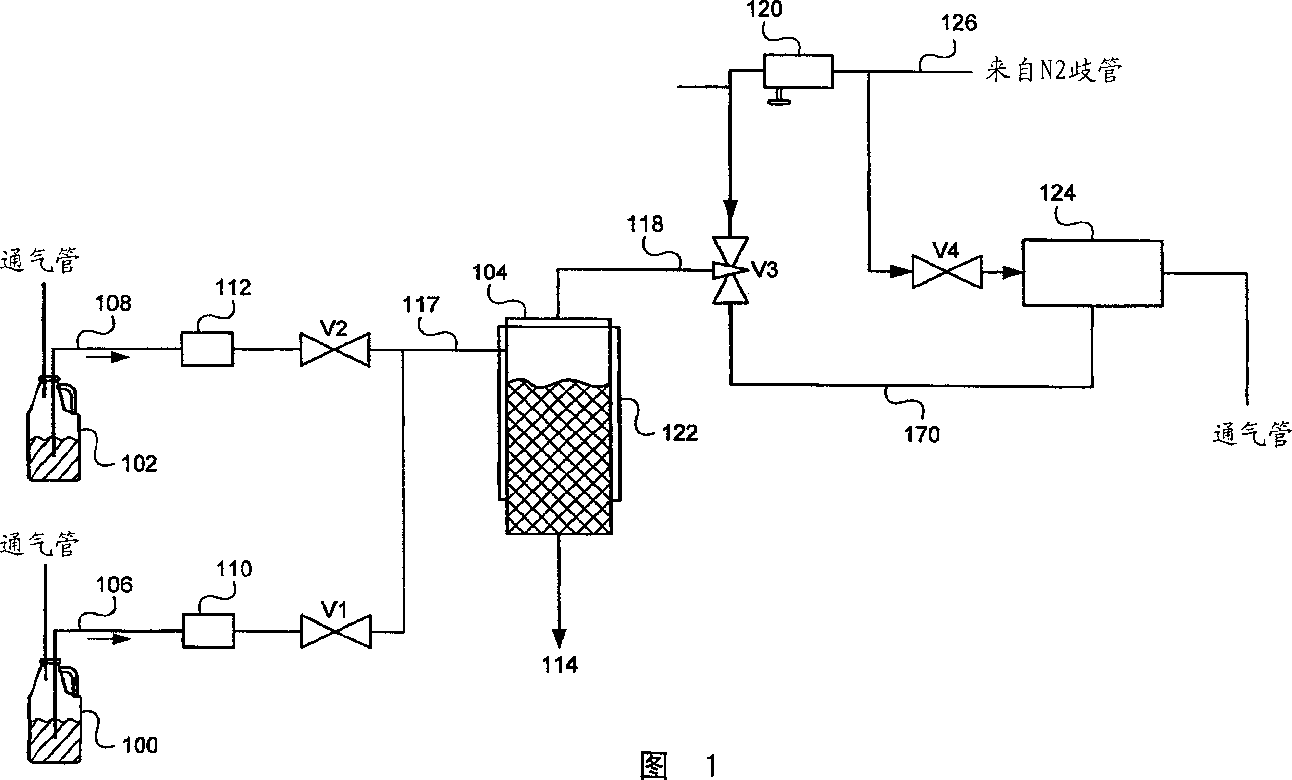
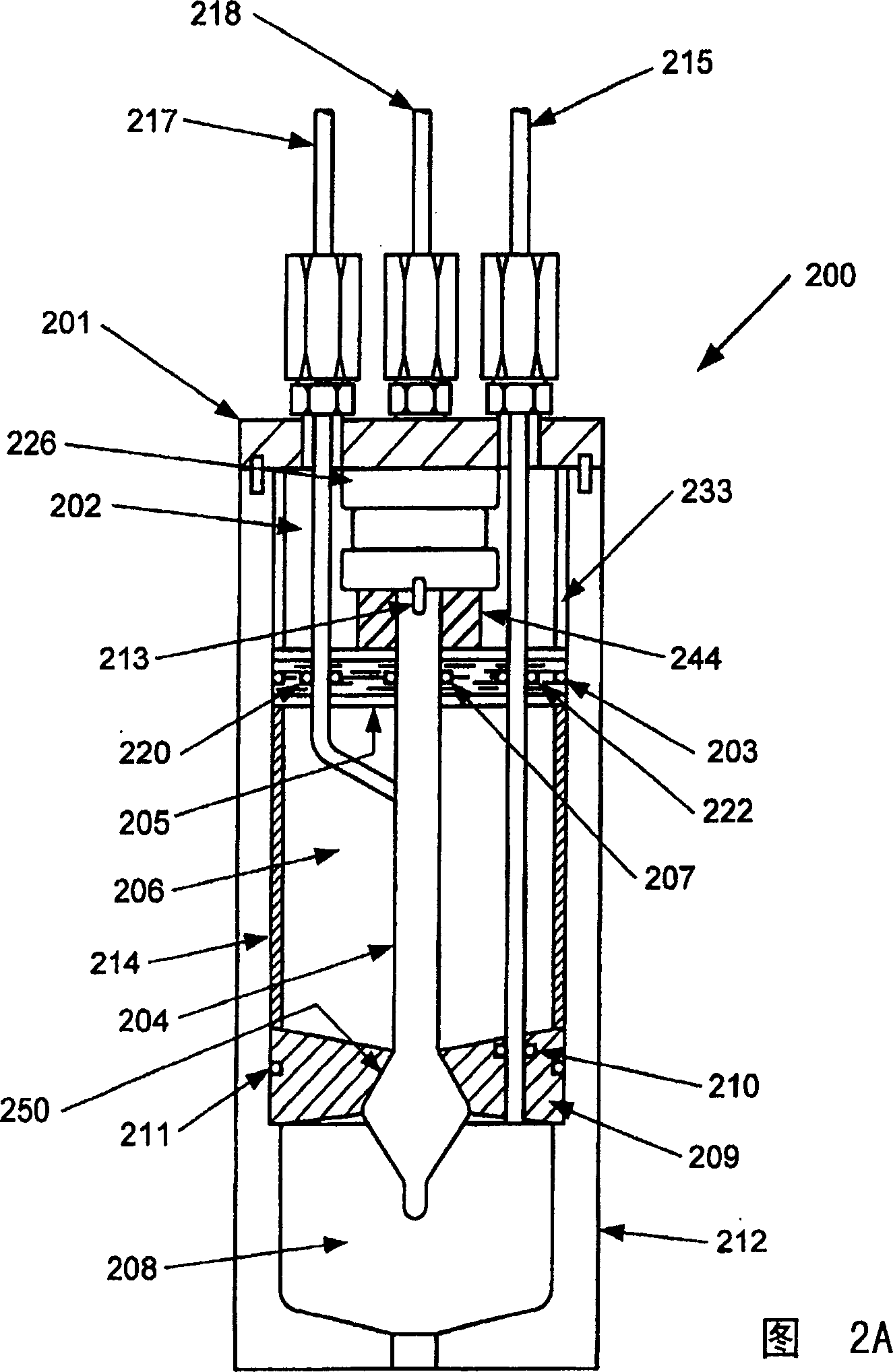
[0033] A first embodiment in accordance with the present invention includes a multi-tank load sensor assembly 200 as shown in FIGS. 2A-2B . The assembly 200 can be as image 3 Part of the system shown, and can replace the problematic single tank 104 and bubble sensors 110, 112 shown in FIG.

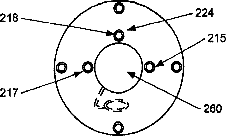
[0034] In this embodiment, the assembly 200, made of Teflon, SST, polypropylene, or any chemically compatible material, includes the upper compartment 202, the main tank 206, and the surge tank all within the housing 912 208. The buffer storage tank 208 is in close contact with the main storage tank 206 through the partition 209 , and the O-ring 211 makes the periphery of the partition 209 closely contact with the casing 212 . A tapered central bore 250 is used in the diaphragm 209 to allow the inner seal shaft 204 to form a liquid and gas tight seal with the diaphragm 209 . The separator 209 forms a liquid-tight and air-tight seal with the pneumatic conduit 215 through an O-ring 210 ....


PUM


Abstract

Chemical delivery systems and methods for delivery of liquid chemicals are disclosed. In on embodiment, systems having multi-reservoir load cell assemblies (Figs. 2, 4, 5, 7, 9, 11) for delivering chemicals used in the semiconductor industry are disclosed. In another embodiment (Fig. 12), the present invention provides a multi reservoir load cell assembly (69, 92, 71), including a controller (PLC), a buffer reservoir (92, 71), a main reservoir (69), one or more load cells (12, 13, 67, 68, 91, 96) coupled to the assembly and to the controller, operable to weigh the liquid in the reservoirs, a plurality of supply lines (A-D), each supply reservoir, and a gas and vacuum sources for withdrawing the liquid from the assembly when demanded by the controller and for refilling the assembly from the supply containers. A proportional valve block including a buffer control Intel (80) and outlet (81) valves adjust the pressure to the buffer reservoirs.

Description

[0001] This application is a continuation-in-part of U.S. Application No. 09 / 968,566, filed September 29, 2001, which is now U.S. Patent No. 6,340,098, filed May 30, 2001 Continuation of Application No. 09 / 870,227, U.S. Application No. 09 / 870,227 is a continuation of U.S. Application No. 09 / 568,926, filed February 13, 2001, now U.S. Patent No. 6,269,975, U.S. Application No. 09 / 568,926 is a continuation of now-abandoned U.S. Application No. 09 / 568,926, filed May 10, 2000, which is now a U.S. Patent filed on December 31, 1998 No. 6,098,843 is a divisional application of U.S. Application No. 09 / 224,607, which is a continuation of now-abandoned U.S. Application No. 09 / 222,003 filed December 30, 1998. This application includes by reference each of the above-listed applications and patents. technical field [0002] The present invention generally relates to systems and methods for mixing and / or delivering liquid chemicals, and more particularly to systems and methods for mixing an...

Claims


Application Information

Patent Timeline
Patent Type & Authority Applications(China)
IPC IPC(8): B01F15/02B67D7/08B01F15/04B67D7/02B67D7/74C30B25/14G01G13/24G01G13/26G01G17/06H01L21/027H01L21/304
CPCB01F15/028B67D7/0272B67D7/74B67D7/0283B01F2215/0036B01F15/0266B01F2215/0096C30B25/14B67D7/08B67D7/0238B01F15/0445B01F35/7543B01F35/75B01F35/881B01F2101/2204B01F2101/58G03F7/26
Inventor 兰迪·福西A·J·肯尼斯
Owner 液化空气电子美国有限公司
Why Eureka
Try Eureka