Supercharge Your Innovation With Domain-Expert AI Agents!

Combined antenna formed by horizontal directivity antenna and zenithal directivity antenna

A combination antenna, horizontal direction technology, applied in antenna combinations with different interactions, mid-position feed between antenna endpoints, antennas, etc., can solve the problems of difficult to provide combined antennas, small size, etc.

Inactive Publication Date: 2005-09-14
DENSO CORP
View PDF2 Cites 4 Cited by
  • Summary
  • Abstract
  • Description
  • Claims
  • Application Information

AI Technical Summary

Problems solved by technology

[0005] Thus, in the prior art, it is difficult to provide this type of combination antenna, wherein this type of combination antenna is provided with a necessary directivity pattern (directivity pattern) for each component antenna, and the size can be made very small

Method used


Image

  • Combined antenna formed by horizontal directivity antenna and zenithal directivity antenna
  • Combined antenna formed by horizontal directivity antenna and zenithal directivity antenna
  • Combined antenna formed by horizontal directivity antenna and zenithal directivity antenna

Examples


Embodiment Construction

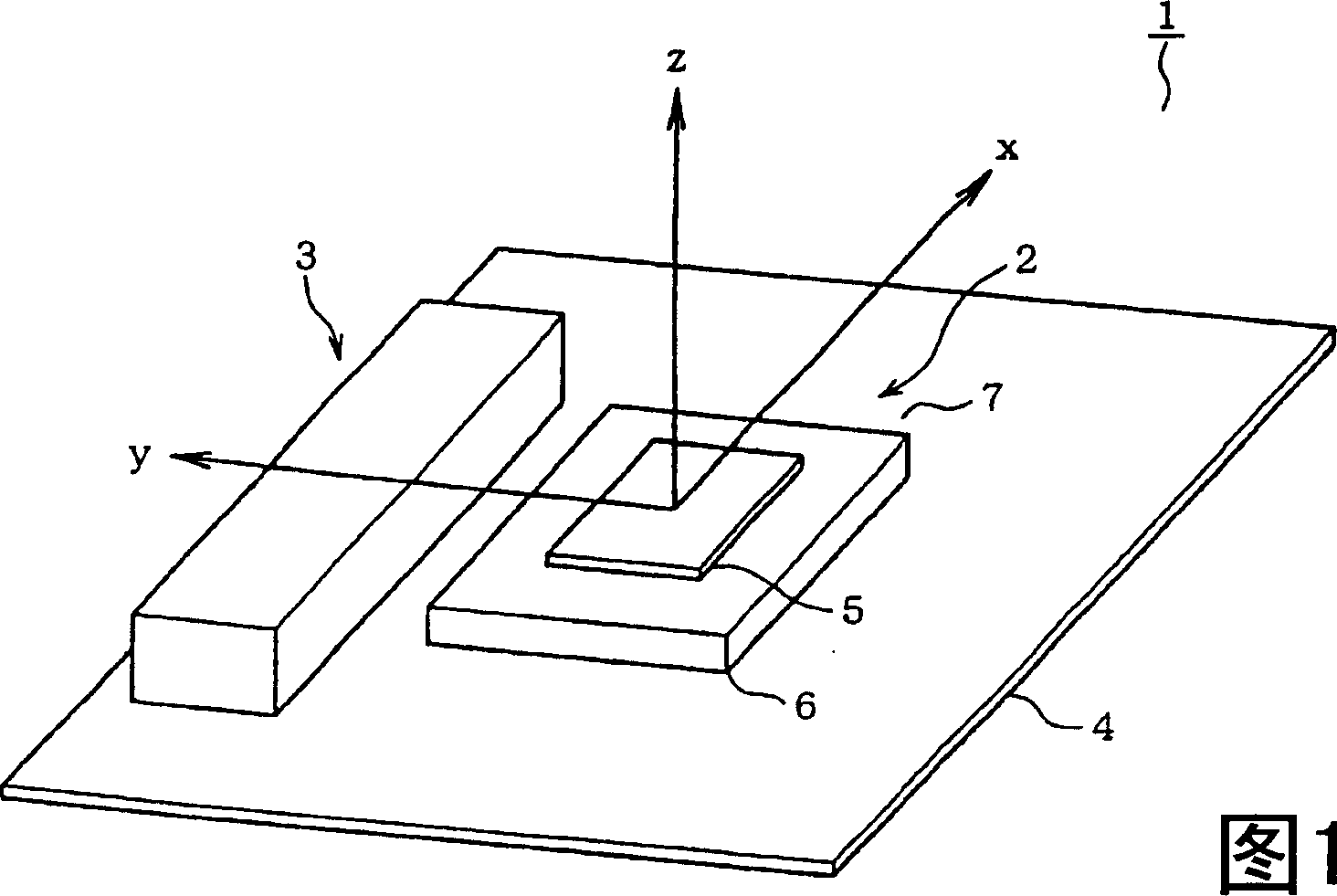
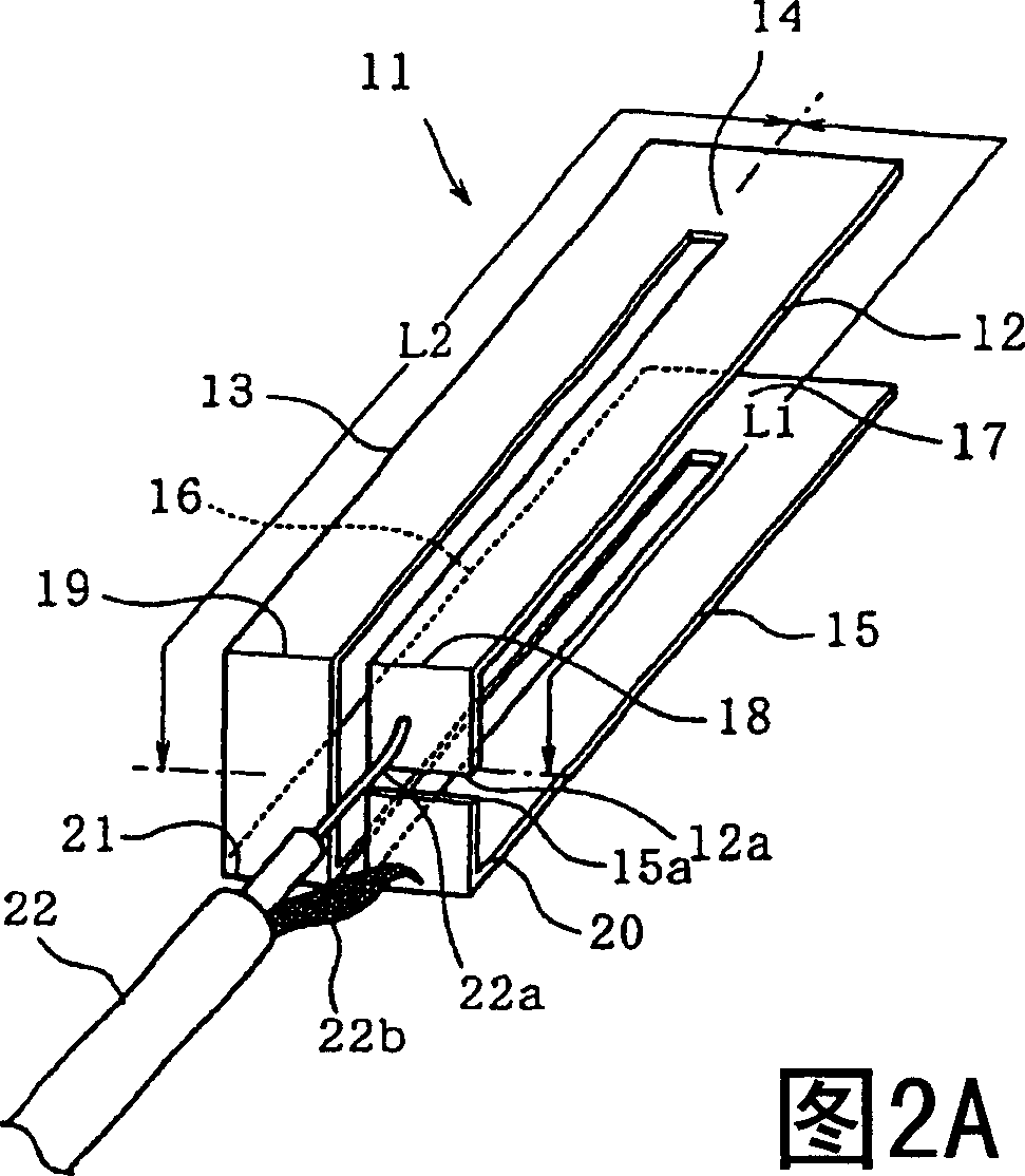
[0023] A first embodiment will be described below, wherein the first embodiment is suitable for use as an on-vehicle antenna. Referring to FIGS. 1 and 2, FIG. 1 is an oblique view, indicated by reference numeral 1, of the general structure of an embodiment of the combined antenna. As shown in the figure, a patch antenna 2 with zenith directivity (for example, an elevation angle of 90°, corresponding to the Z direction shown in FIG. 1 ) and a patch antenna 2 with horizontal directionality (for example, an elevation angle of 0°) are formed. Antenna3.

[0024] The patch antenna 2 is formed by a heat sink element 5 configured as a metal plate on an insulator 6 , while the insulator 6 is arranged centrally on the upper surface of the ground plate 4 . The insulator 6 is formed of a material such as synthetic resin.

[0025] The chip antenna 2 may be, for example, a GPS (Global Positioning System) antenna for receiving radio waves transmitted from satellites of the GPS system, or a...


PUM


Abstract

A combined antenna is disclosed in the invention, includes antennas respectively having horizontal directivity and meridian directivity, and a ground plate for operating at least the antenna having meridian directivity. The antenna having meridian directivity is arranged in the vicinity of the central part of the ground plate, Meanwhile, the antenna having the horizontal directivity is arranged in the vicinity of the periphery of the ground plate. The horizontal directivity antenna can be in an improved folded dipole structure, thus the combined antenna can obtain lower outline and compact size, meanwhile, each antenna component of the combined antenna can have satisfying directional pattern.

Description

[0001] Cross References to Related Applications [0002] This application is based on Japanese Patent Application No. 2004-069054 filed on Mar. 11, 2004, which is hereby incorporated by reference. technical field [0003] The present invention relates to a composite antenna composed of a first antenna having directivity in a predetermined direction, a ground plate serving as a ground of the first antenna, and a second antenna having directivity in a horizontal direction. Background technique [0004] In the prior art, there are several examples of combined antennas with multiple antennas sharing a common ground plane, as described in Japanese Patent Laid-Open No. 2003-168917. However, with this prior art type of combined antenna, each component antenna has directivity in a meridian direction, for example, at an elevation angle of about 90°, so that each antenna can use a single ground plane as a common ground. Wire. In recent years, with the development of radio communicat...

Claims


Application Information

Patent Timeline
Patent Type & Authority Applications(China)
IPC IPC(8): H01Q21/29H01Q1/32H01Q5/00H01Q9/16H01Q13/08H01Q21/00
Inventor 三上成信山崎彻林昭彦大原克博
Owner DENSO CORP
Features
  • R&D
  • Intellectual Property
  • Life Sciences
  • Materials
  • Tech Scout
  • Unparalleled Data Quality
  • Higher Quality Content
  • 60% Fewer Hallucinations
Learn More