Dynamoelectric machine having an encapsulated coil structure

A technology of coil and lamination structure, applied in the manufacture of motor generators, magnetic circuit shape/style/structure, coils, etc., can solve the problem of large armature and achieve the effect of increasing torque

Inactive Publication Date: 2005-09-14
BLACK & DECKER INC
View PDF0 Cites 24 Cited by
  • Summary
  • Abstract
  • Description
  • Claims
  • Application Information

AI Technical Summary

Problems solved by technology

However, using larger gauge wire to wind the magnet wire will generally require a larger slot to accommodate the required

Method used


Image

  • Dynamoelectric machine having an encapsulated coil structure
  • Dynamoelectric machine having an encapsulated coil structure
  • Dynamoelectric machine having an encapsulated coil structure

Examples


Embodiment Construction

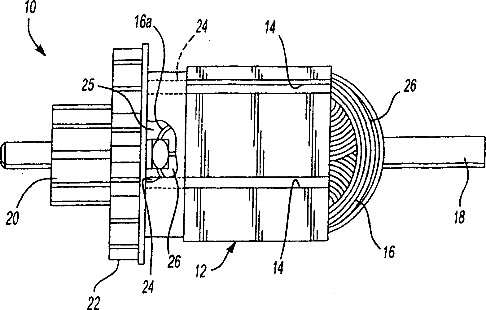
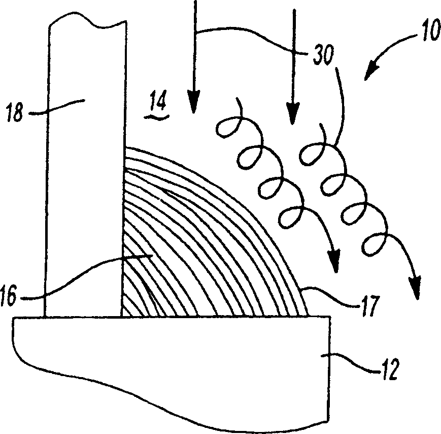
[0077] see now Figure 5 , discloses a motor 100 according to a preferred embodiment of the present invention. The electric machine 100 includes an armature 102 and a stator 104, which is shown in a very simplified manner. The armature 102 includes a laminated structure 106 having a plurality of longitudinal slots 108 circumferentially disposed thereabout. A plurality of magnet wires 110 are wound in slots 108 to form a plurality of coil windings with end coils 117 . An armature shaft 112 extends coaxially through the laminated core 106 and carries a commutator 114 at one end thereof. Thermally conductive plastic 116 is injection molded onto armature 102 such that the plastic flows into and through each slot 108 . The thermally conductive plastic 116 is applied by placing the armature 102 in a suitable injection molding tool and then injecting the thermally conductive plastic 116 into the molding tool at a suitable high pressure. The thermally conductive plastic 116 prefera...


PUM


Abstract

Magnet wires wound in slots in a lamination stack of a dynamoelectric machine are encapsulated, in whole or in part, with plastic. The plastic may be thermally conductive and have features molded therein that enhance heat transfer. The plastic may stiffen the armature and increase its critical speed. Characteristics of the plastic, its geometry and its distribution may be varied to adjust spinning inertia and resonant frequency of the armature. The magnet wires may be compressed into the slots, by application of iso-static pressure or by the pressure of the plastic being molded around them. Larger magnet wire can then be used which increases the power of the electric motor using the armature having the larger magnet wire. A two or three plate mold may be used to mold the plastic around the armature. Balancing features can be molded in place. The plastic can have a base polymer that is a blend of two or more polymers and various thermally conductive fillings.

Description

technical field [0001] The present invention relates to dynamoelectric machines, and more particularly to a dynamoelectric machine having a coil structure encapsulated with thermally conductive plastic. Background technique [0002] A motor generator is a machine that produces or uses electricity. Common types of motor generators are alternators, generators and electric motors. [0003] Electric motors are used in a wide variety of applications including power tools such as drills, saws, sanding devices, yard tools such as edgers and trimmers, just to name a few examples of such tools. These devices all utilize an electric motor with an armature and a field such as a stator. The armature is usually formed from a laminated structure or core wound by multiple windings of magnet wire. The laminated structure is formed with a plurality of poles on which the magnet wire is wound. In this regard, the laminated structure may be formed with a plurality of slots into which the ma...

Claims


Application Information

Patent Timeline
IPC IPC(8): H01F5/00B29C45/14H02K1/30H02K1/32H02K3/12H02K3/30H02K3/34H02K3/44H02K3/46H02K3/48H02K3/487H02K3/50H02K7/04H02K9/20H02K9/22H02K13/00H02K13/04H02K15/12H02K15/16
CPCH02K15/12H02K13/006H02K7/04H02K3/345H02K3/50H02K1/30H02K9/20H02K3/46H02K1/32B29C45/14639H02K3/30H02K3/487H02K13/04H02K3/12H02K9/22H02K3/48H02K15/165H02K9/227H02K9/223
Inventor H·T·杜B·费尔布鲁格J·维斯特M·塞尔R·T·沃尔特D·J·史密斯E·M·奥尔特J·C·斯通H·怀特
Owner BLACK & DECKER INC
Why Eureka
Try Eureka