

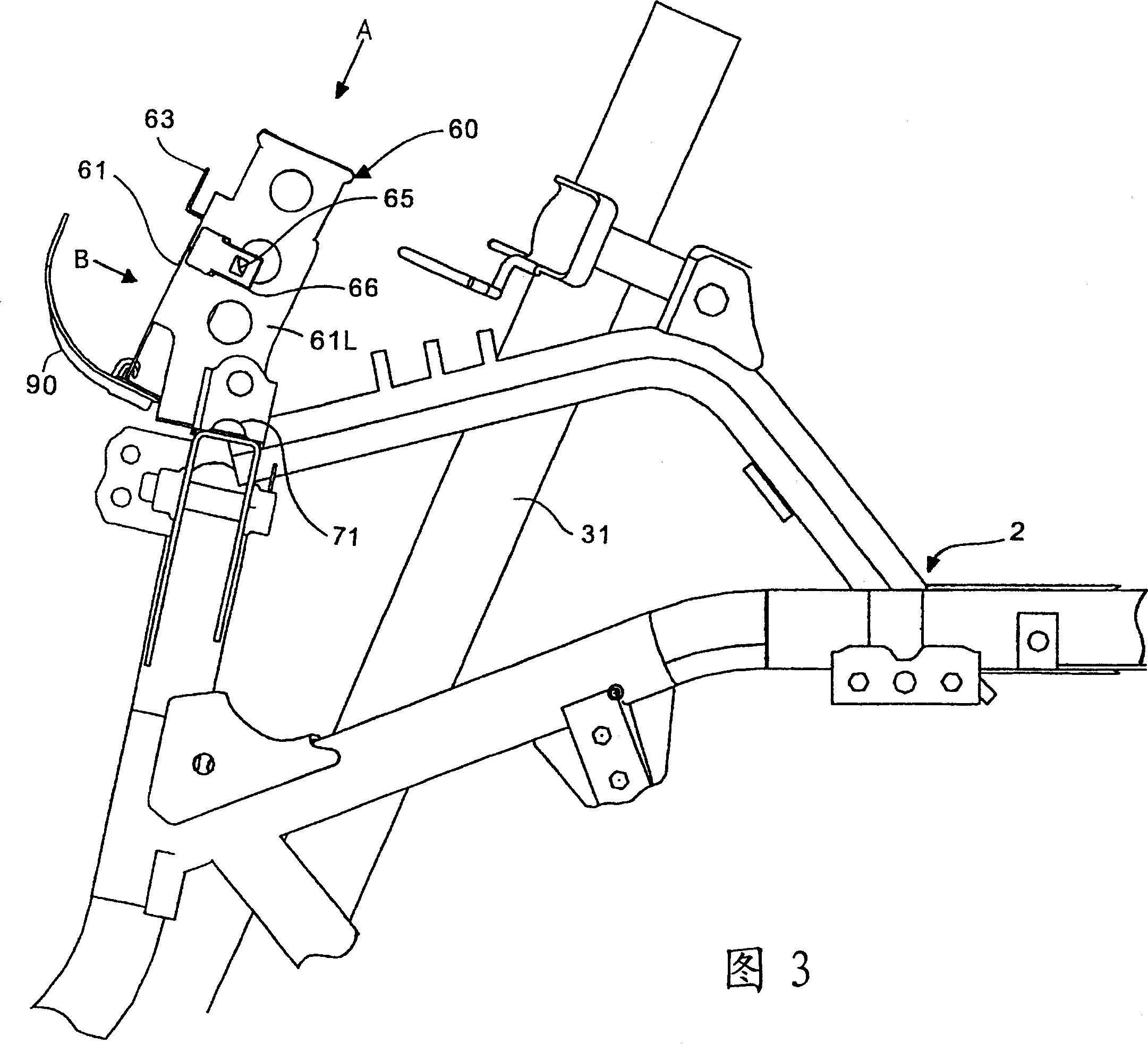
Control box mounting bracket
一种安装托架、控制箱的技术,应用在动力装置控制机构的布置、摩托车、运输和包装等方向,能够解决安装位置限制、升高等问题,达到缓和振动和冲击的效果
- Summary
- Abstract
- Description
- Claims
- Application Information
AI Technical Summary
Problems solved by technology
Method used
Image

Examples
Embodiment Construction
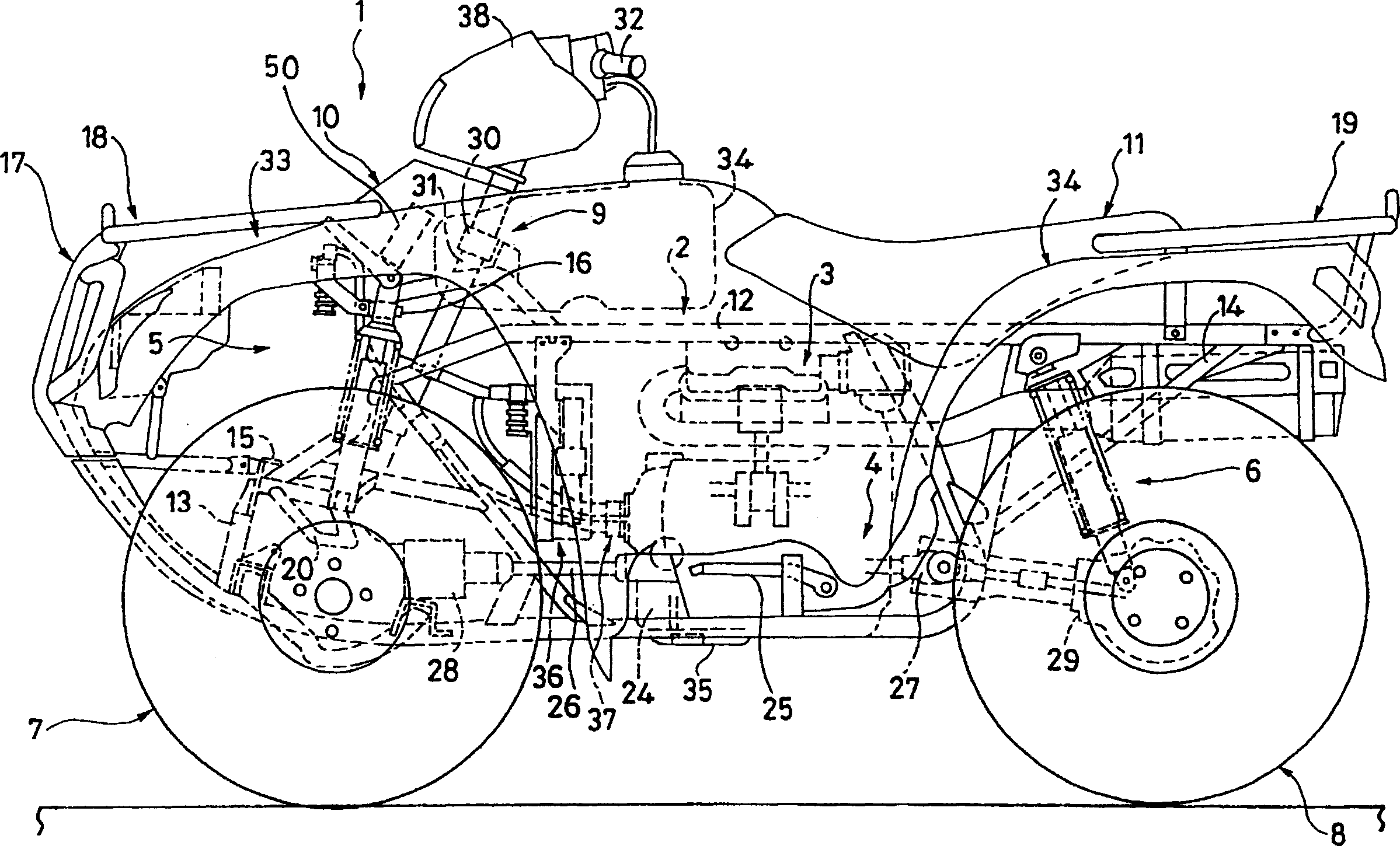
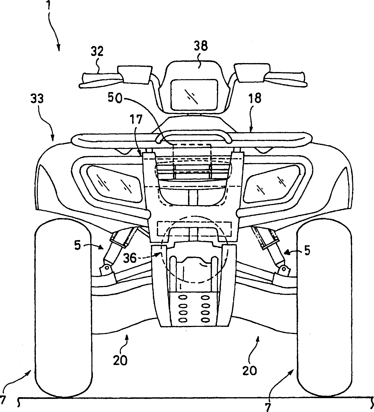
[0036] Hereinafter, preferred embodiments of the present invention will be described in detail with reference to the accompanying drawings. figure 1 is a side view of an ATV supporting an engine control box utilizing the control box mounting bracket of the present invention, figure 2 is its front view.
[0037] ATV1 comprises a vehicle frame 2, a four-stroke engine 3 installed on the central lower part of the vehicle frame 2, a power transmission device 4 installed on the vehicle frame 2 and connected with the engine 3, and the front and rear of the power transmission device 4 are maintained to be relatively Vehicle frame 2 freely swings front suspension 5 and rear suspension 6. The front wheels 7 are supported on the left and right front of the power transmission device 4 , and the rear wheels 8 are supported on the left and right rear of the power transmission device 4 . The front wheel 7 and the rear wheel 8 are connected to the vehicle frame 2 through the front suspensi...
PUM
 Abstract
Description
Claims
Application Information