Balance oscillating dyeing machine

An oscillating and balanced technology, which is applied in vibration treatment, dyeing equipment for textile materials, textiles and papermaking, etc., can solve problems such as trouble-free working time, noise pollution, and large vibration that affect the service life of the crank-link mechanism. , to achieve the effect of simple structure, stable operation and low noise

Inactive Publication Date: 2005-10-05
张同生
View PDF0 Cites 12 Cited by
  • Summary
  • Abstract
  • Description
  • Claims
  • Application Information

AI Technical Summary

Problems solved by technology

The most commonly used test equipment is the oscillating dyeing machine. During the test, put a series of dyes and gray cloths with different formulas into corresponding beakers, and then fix the beakers in the oscillating box, which is installed in a water tank with a heating device. It can reciprocate left and right (or back and forth) in the water tank, so that the dye in the beaker shakes and the dye is evenly and thoroughly combined with t

Method used


Image

  • Balance oscillating dyeing machine
  • Balance oscillating dyeing machine

Examples


Embodiment 1

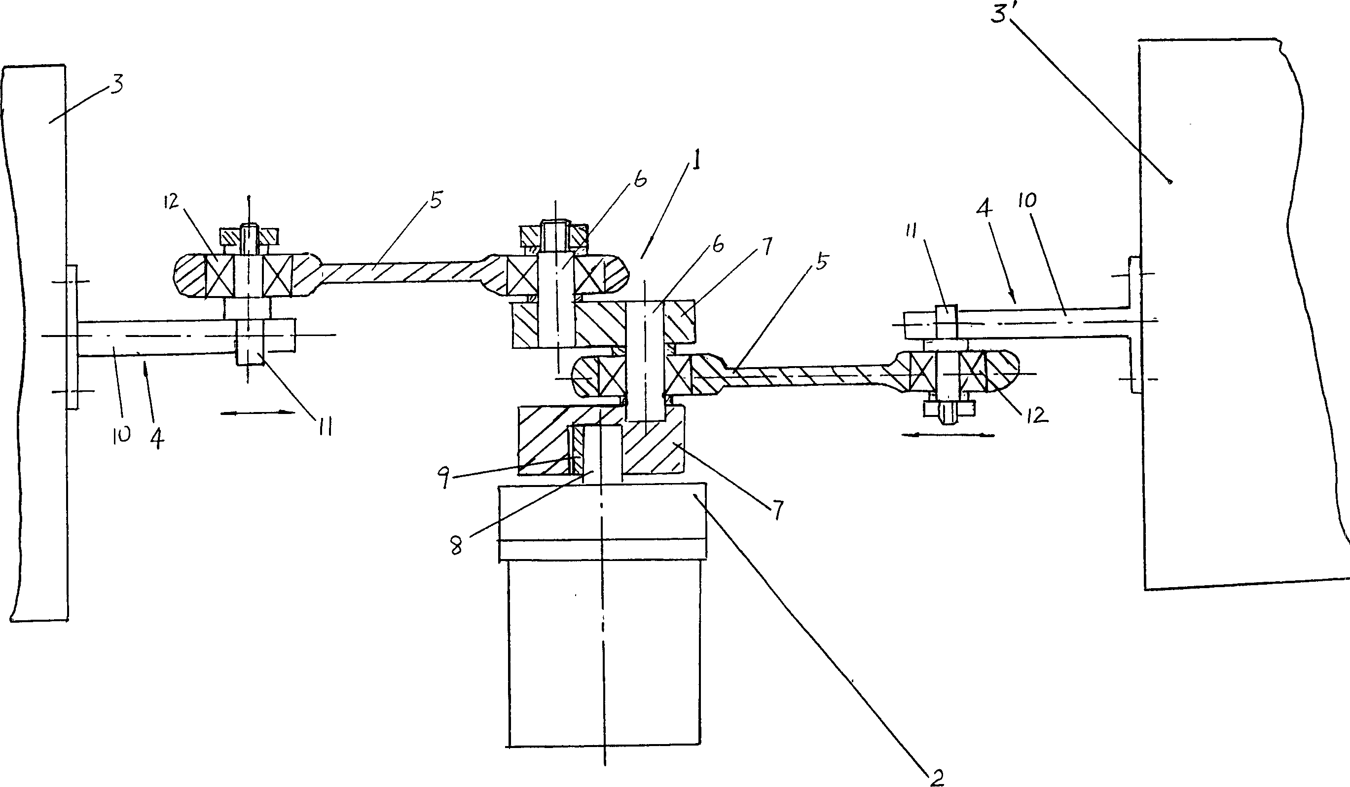
[0018] like figure 1 As shown, a balanced oscillating dyeing machine includes a crank-link mechanism 1. The crank-link mechanism 1 is at least composed of two crank discs 7, two cranks 6 and two connecting rods 5. One crank 6 is located on two Between the crank plates 7, another crank 6 is suspended on one crank plate 7, and the center of the other crank plate 7 is provided with a connecting hole with a keyway, which drives the output shaft 8 of the power assembly 2 of the whole crank linkage mechanism 1 to rotate. Inserted into the connection hole and connected to the crank plate 7 through the key 9, the crank plate 7 and the crank 6 in the crank linkage mechanism 1 can be an integral structure, or a split combined structure, and this embodiment is a split structure; Power assembly 2 can adopt the motor or speed-regulating motor that has reduction box, also can be the motor of belt deceleration, can also be diesel engine etc., what present embodiment adopted is the motor that...

Embodiment 2

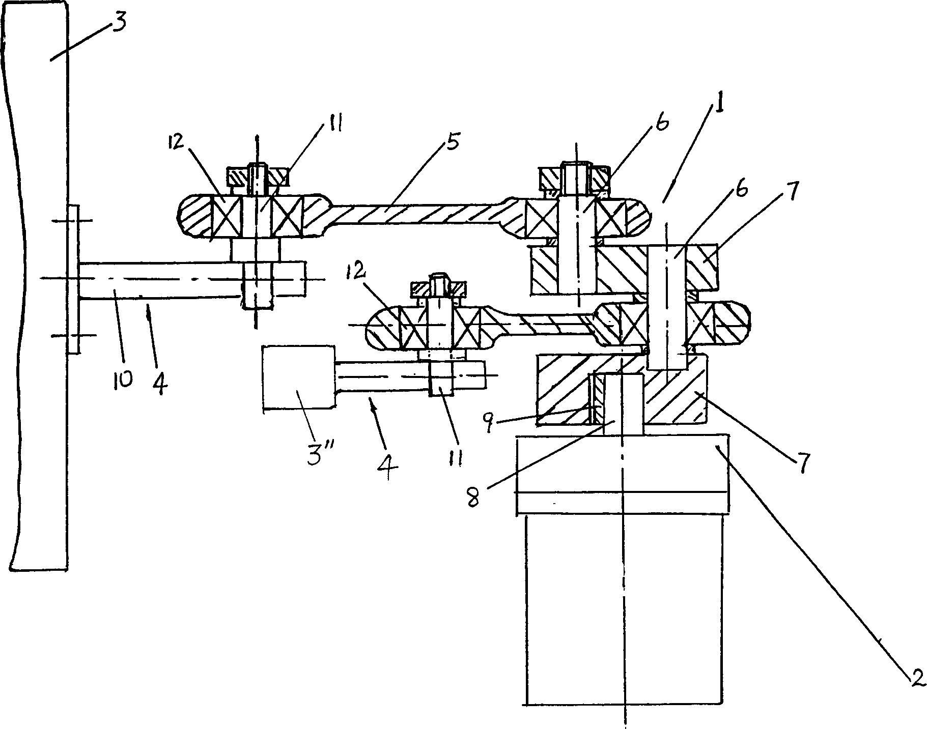
[0022] like figure 2 shown.

[0023] The difference between the present embodiment and the first embodiment is that the balance weight 3 " (the vibration box 3 ' can also be used in specific implementation) and the vibration box 3 are both located at the center axis of the crank connecting rod mechanism 1. On the same side, the balance weight 3 "can adopt a metal block, and its weight is determined after the counterweight calculation.

[0024] The other parts of this embodiment are the same as those of Embodiment 1.


PUM


Abstract

This invention discloses a kind of balanced concussion coloring machine which can keep the apparent force almost in balance when the crank mechanical linkage is working which can drive the concussing box moving. So the vibration is small while the jar is low and the abrade is small. As a result, we can substantially elongate the machine's non-accident working time and using life length. It includes the crank mechanical linkage (1), concussion box(3), and (3) whose reciprocation is driven by (1) is linked with (1) and is fixed on one side of (1). The invention's characters are that not only does (1 has (3) on its side, but also it has another concussion box(3`) or (3``)on the other side to balance the apparent force of (1). (3),(3') and (3``) are linked with one end of the connection bar(5) of (1), while the other end is linked with the crank(6) corresponding to (1).

Description

technical field [0001] The invention relates to a test equipment used in the printing and dyeing industry, in particular to a balanced oscillating dyeing machine. Background technique [0002] At present, in the printing and dyeing industry, in order to obtain the printing and dyeing formula and temperature closest to the designed color, so as to facilitate large-scale production, the best formula must be obtained through experiments. The most commonly used test equipment is the oscillating dyeing machine. During the test, put a series of dyes and gray cloths with different formulas into corresponding beakers, and then fix the beakers in the oscillating box, which is installed in a water tank with a heating device. It can reciprocate left and right (or back and forth) in the water tank, so that the dye in the beaker shakes and the dye is evenly and thoroughly combined with the gray cloth. The left and right (or front and back) movement of the oscillation box is driven by a c...

Claims


Application Information

Patent Timeline
IPC IPC(8): D06B13/00D06B23/10
Inventor 张同生
Owner 张同生
Why Eureka
Try Eureka