Supercharge Your Innovation With Domain-Expert AI Agents!

Weight-light ligh-emitting diode unit

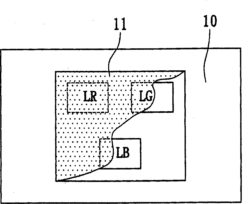
A technology of light-emitting diodes and white light, applied in luminescent materials, electrical components, sustainable buildings, etc.

Active Publication Date: 2005-10-05
HARVATEK CORPORATION
View PDF0 Cites 21 Cited by
  • Summary
  • Abstract
  • Description
  • Claims
  • Application Information

AI Technical Summary

Problems solved by technology

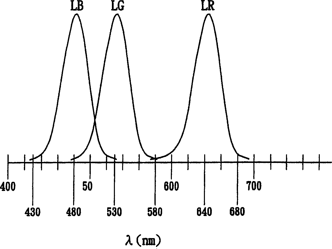
[0005] The main purpose of the present invention is to provide a white light emitting diode unit with both luminous efficiency and color rendering, so as to solve the above-mentioned shortcomings of the existing white light emitting diodes

Method used


Image

  • Weight-light ligh-emitting diode unit
  • Weight-light ligh-emitting diode unit
  • Weight-light ligh-emitting diode unit

Examples


Embodiment Construction

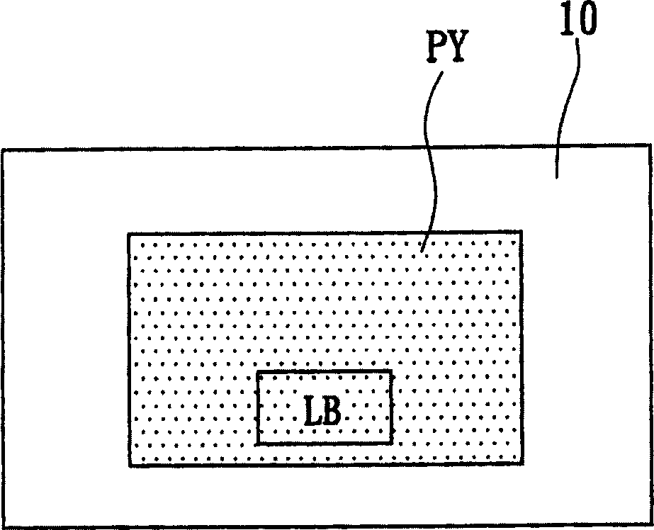
[0014] Such as image 3 Shown is a schematic diagram of a white light emitting diode unit 2 according to a preferred embodiment of the present invention. The white light emitting diode comprises a substrate 20, a blue light emitting diode LB positioned on the substrate 20, and a red phosphor PR and a green phosphor PG positioned on the blue light emitting diode LB, the red phosphor PR and the green phosphor The phosphor PG can absorb the blue light of the blue light-emitting diode LB to emit red light and green light respectively, and mix with the blue light of the blue light-emitting diode LB to form white light.

[0015] Among the red and green phosphors described above, the red phosphor can use Cas:Eu or SrS:Eu; the yellow silver phosphor can use YAG:Ce or TbAG:Ce; and the green phosphor can use SrGa 2 S 4 : Eu or Ca 8 EuMnMg(SiO 4 ) 4 C 12 . However, it should be noted that there are other phosphors that can be used besides the above-mentioned phosphors, but it does...


PUM


Abstract

White light LED comprises following parts: a substrate, a blue light LED on the substrate, a mixed fluorophor including red, green, and yellow fluorophors, which are covered outer side of blue light LED. Red fluorophor can be CaS : Eu or SrS : Eu; yellow fluorophor can be YAG : Ce or TbAG :Ce, and green fluorophor can be SrGa2S4 : Eu or Ca8EuMnMg(SiO4)4 Cl12. High color rendering white light is obtained by mixing red, green and yellow lights with blue light from blue light LED.

Description

technical field [0001] The invention relates to a white light emitting diode unit, in particular to a white light emitting diode unit having both luminous efficiency and color rendering. Background technique [0002] White light is multi-color mixed light, which can be perceived as white light by human eyes, and includes at least two or more wavelengths of mixed light. For example, when the human eye is stimulated by red, blue, and green light at the same time, or when it is stimulated by blue light and yellow light at the same time, it can be perceived as white light. Therefore, a semiconductor light emitting device capable of emitting white light can be manufactured according to this principle. The manufacturing methods of the existing white light semiconductor light emitting devices are described as follows. [0003] The first way is to use three red, blue and green light-emitting diodes made of aluminum gallium indium phosphide (AlInGaP), indium gallium nitride (InGaN)...

Claims


Application Information

Patent Timeline
IPC IPC(8): C09K11/77H01L33/00
CPCY02B20/181Y02B20/00
Inventor 汪秉龙庄峰辉林川发余志善
Owner HARVATEK CORPORATION
Features
  • R&D
  • Intellectual Property
  • Life Sciences
  • Materials
  • Tech Scout
  • Unparalleled Data Quality
  • Higher Quality Content
  • 60% Fewer Hallucinations
Learn More