Sampling rate converting system and filtering method
一种变换装置、比率的技术,应用在抽样比率变换装置领域,能够解决没有考虑输入图像信号、折返干扰和图像质量变差等问题,达到高质量变换图像质量、抑制折返干扰的效果
- Summary
- Abstract
- Description
- Claims
- Application Information
AI Technical Summary
Problems solved by technology
Method used
Image

Examples
no. 1 approach
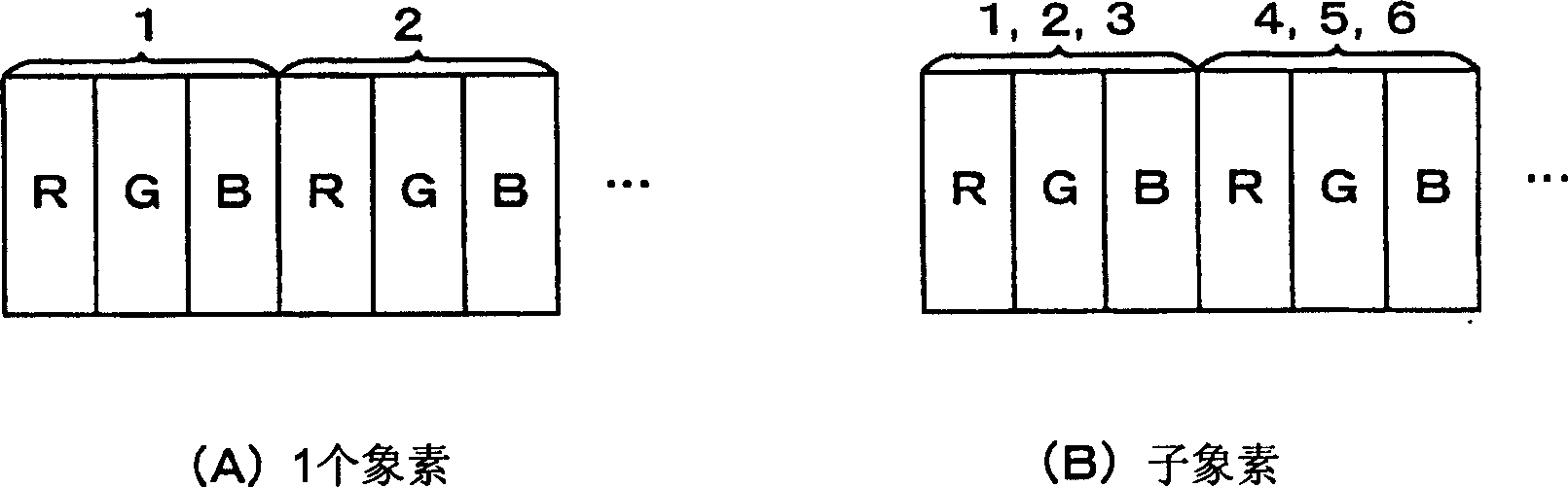
[0062] First, with reference to the drawings, the number of pixels conversion (hereinafter referred to as "sub-pixel rendering technology") applied to the sampling rate conversion device according to the first embodiment of the present invention (Sub-pixel Rendering Technology) "Pixel Number Conversion") for description.
[0063] Sub-pixel rendering techniques are generally as figure 1 As shown in (A), a pixel is constituted by three sub-pixels of RGB, as opposed to this, as figure 1 As shown in (B), each sub-pixel is regarded as one pixel, and luminance is reproduced for each sub-pixel.
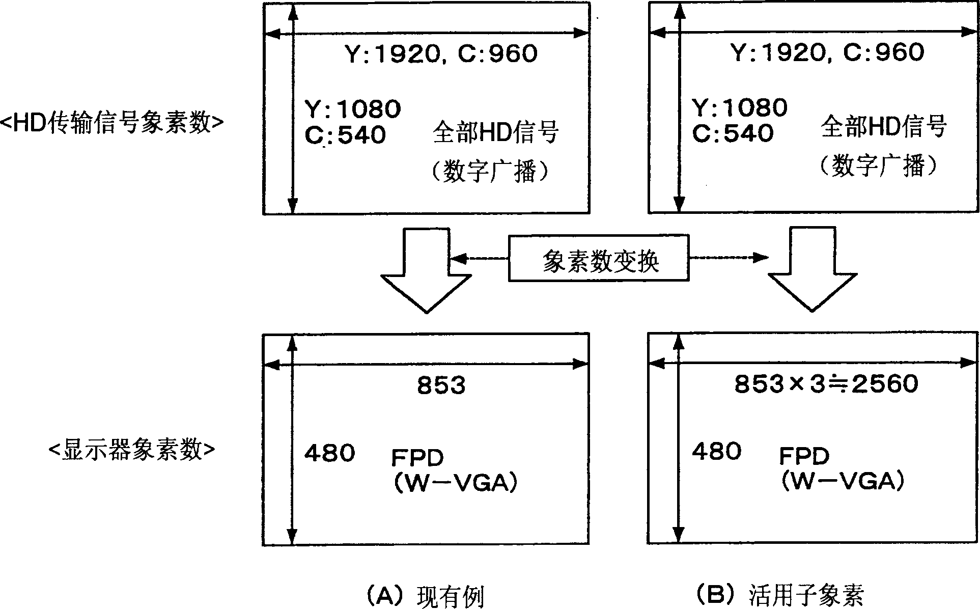
[0064] image 3 (B) is a diagram showing a conversion model of the sub-pixel number of pixels for displaying a high-definition image whose number of pixels is larger than that of a display. Here, since the sub-pixels of RGB are sequentially arranged in the horizontal direction, the number of pixels in the horizontal direction becomes 2560 pixels (853×3 pixels). Strictly speaking, this i...
no. 2 approach
[0104] Figure 17 It is a block diagram showing the configuration of the sampling rate conversion device according to the second embodiment of the present invention. Here, the same symbols are assigned to the same constituent elements as those of the device according to the first embodiment.
[0105] The sampling rate conversion device according to the second embodiment has a sub-pixel pixel number converter 1, a sub-pixel oversampling filter 8, a second pixel unit pixel number converter 3, an image feature detector 4a, a mixing Device 5, YUV→RGB matrix converter 6.
[0106] Sub-pixel pixel number converter 1 utilizes sub-pixel pixel number conversion, output such as Image 6 with Figure 7 For the brightness signal Y2 of 2560cpL output in (D), the second pixel unit pixel number converter 3 outputs a color difference signal of 853cpL. Here, the output luminance signal Y2 of the sub-pixel pixel number converter 1 and the output color difference signals U and V of the second...
no. 3 approach
[0112] Figure 19 It is a diagram for explaining the pixel completion variable filtering process applied to the sampling ratio conversion device of this embodiment. In this diagram, the horizontal direction corresponds to the time axis which is the horizontal direction on the display.
[0113] Figure 19 (A) shows the pixel arrangement related to the horizontal direction of the display, Figure 19 (B) shows the luminance signal after sub-pixel pixel number conversion, that is, Figure 7 (D) The data column of the luminance signal of 2560 cpL. In this data sequence, the luminance signal changes in time series (t1 to t12). Figure 19 (C) to (F) show pixel-complete variable filters that change with time series (t1 to t12). Figure 19 The "mark" in (C) to (F) is an output sampling point, and indicates the phase of the luminance signal corresponding to each RGB sub-pixel of the display and after converting the number of sub-pixels. The output sampling point and the time elapse...
PUM
 Abstract
Description
Claims
Application Information
 - R&D
- Intellectual Property
- Life Sciences
- Materials
- Tech Scout
- Unparalleled Data Quality
- Higher Quality Content
- 60% Fewer Hallucinations
Browse by: Latest US Patents, China's latest patents, Technical Efficacy Thesaurus, Application Domain, Technology Topic, Popular Technical Reports.
© 2025 PatSnap. All rights reserved.Legal|Privacy policy|Modern Slavery Act Transparency Statement|Sitemap|About US| Contact US: help@patsnap.com