Engineering machinery cooling device collocating structure

A technology for cooling devices and construction machinery, which is applied in the direction of engine cooling, mechanical equipment, and the arrangement of cooling combination of power devices, etc., which can solve the problems of shrinking heat exchanger configuration space, increasing manufacturing man-hours, and increasing manufacturing costs. Effect of miniaturization, reduction of production cost, and reduction of production man-hours

Inactive Publication Date: 2005-11-02
HITACHI CONSTR MASCH CO LTD
View PDF1 Cites 6 Cited by
  • Summary
  • Abstract
  • Description
  • Claims
  • Application Information

AI Technical Summary

Problems solved by technology

[0003] Since the above-mentioned prior art is provided with a windshield part as an independent part between the wall member arranged on the main body and the heat sink, the number of parts is large, and the manufacturing man-hours are increased accordingly, and the manufacturing cost is increased.
In addition, related to the recent demand for miniaturization of construction machinery, the arrangement space of the heat exchanger needs a small space, and it is particularly desired to reduce the size of the main body in the front-rear direction in the direction connecting the two sides of the heat exchanger. However, due to the In the prior art, a relatively large windshield is arranged between the heat exchanger and the wall member, so it is difficult to reduce the arrangement space of the heat exchanger

Method used


Image

  • Engineering machinery cooling device collocating structure
  • Engineering machinery cooling device collocating structure
  • Engineering machinery cooling device collocating structure

Examples


Embodiment Construction

[0021] The best mode of the cooling device arrangement structure for the construction machine for carrying out the present invention will be described below with reference to the drawings.

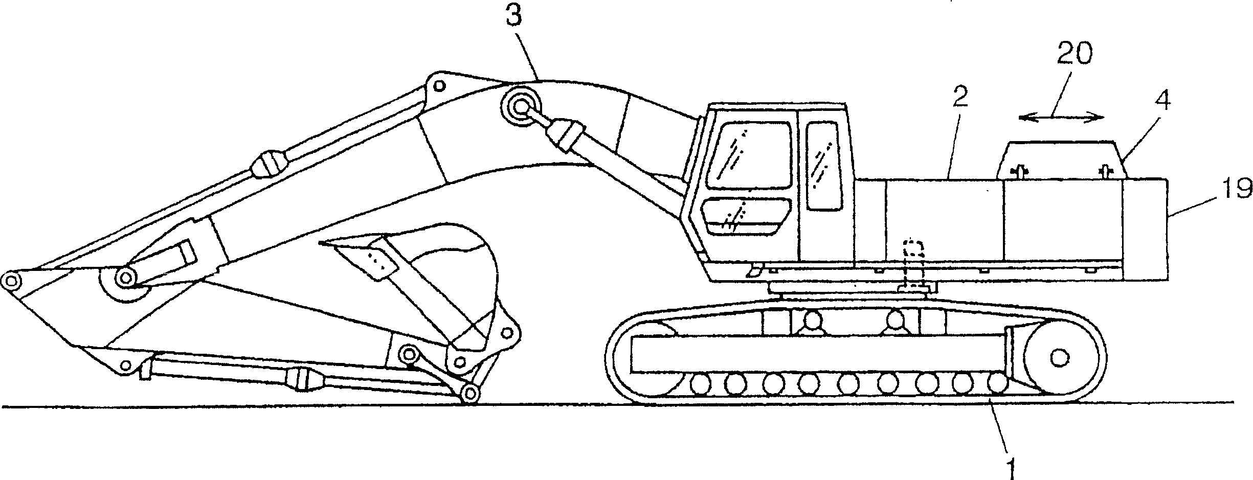
[0022] figure 1 As an example of a construction machine, a side view of a hydraulic excavator provided with the first embodiment of the construction machine cooling device arrangement structure of the present invention is shown.

[0023] Should figure 1 The hydraulic excavator shown has: a walking body 1; a main body arranged on the walking body 1, that is, a revolving body 2; The machine 3 includes a boom, a boom, a bucket, and the like. The revolving body 2 is provided with an engine room 4 which is a cabin, and the engine room 4 is provided with the first embodiment of the arrangement structure of the cooling device which is the object of the present invention. In addition, the figure 1 Reference numeral 19 in the figure indicates a counterweight for ensuring weight balance, and 20 ...


PUM


Abstract

This inveniton provides a cooling device disposition structure of a construction machine, decreasing the number of parts and reducing the disposition space of a heat exchanger. In this structure, a cooling device including an oil cooler 7, a radiator 8 and a cooling fan 10 for cooling the oil cooler 7 and the radiator 8 is disposed in a revolving structure 2 of a hydraulic shovel. The radiator 8 is disposed so that both side parts of the radiator 8 are respectively opposite to a front wall member 4a and a rear wall member 4b which are members constituting an engine room 4. A first projecting part 8a and a second projecting part 8b are formed on both side parts of the radiator, respectively, and a first seal member 11 sealing a gap between the first projecting part 8a and the front wall member 4a and a second seal member 12 sealing a gap between the second projecting part 8b and the rear wall member 4b are provided.

Description

technical field [0001] The invention relates to a cooling device arrangement structure of construction machinery, which is used to arrange a cooling device in the main body of construction machinery such as a hydraulic excavator. The cooling device includes: a heat exchanger such as a radiator, and an induction cooling heat exchanger. Cooling fan unit for cooling air. Background technique [0002] Such prior art includes, for example, the technology described in Japanese Patent Application Laid-Open No. 11-93664. This prior art is to arrange a cooling device inside the hood of the main body of the engine working machine, that is, the inside of the wall member, and the cooling device includes a radiator, that is, a heat exchanger; Cooling fan, that is, cooling fan. The larger windshield part is interposed between the heat exchanger and the wall member, and a sealing tape, that is, a sealing member is arranged on the outer edge of the windshield part. The sealing member is m...

Claims


Application Information

Patent Timeline
IPC IPC(8): E02F9/00B60K11/04F01P3/18F01P5/06
CPCH03F1/52H03F2200/231H03F2200/471
Inventor 原本英毅荒井康枡川康雄
Owner HITACHI CONSTR MASCH CO LTD
Why Eureka
Try Eureka