Electric fan head tilting angle regulating device

A technology for regulating devices and electric fans, which is applied to pump devices, pump control, non-variable pumps, etc., and can solve the problems that the baffle cannot block the swing rod and the angle adjustment operation fails.

Inactive Publication Date: 2005-11-02
蒋亮健
View PDF2 Cites 6 Cited by
  • Summary
  • Abstract
  • Description
  • Claims
  • Application Information

AI Technical Summary

Problems solved by technology

[0002] In the prior art, in the patented inventions "Electric Fan Swing Angle Adjustment Device" (ZL89100824) and "Electric Fan Swing Angle Adjustment Device" (Application No. 00117492.4), a user preset swing angle value is shown. , the automatic angle adjustment system that automatically completes the angle adjustment by the electric fan itself, referring to the original text, we can see that the angle adjustment system is composed of a housing, a worm-worm gear-gear reduction mechanism, a variable length crank mechanism of a planetary gear system, a ratchet pawl clutch, a cam- Swing rod sampler, swing rod-push plate ratchet control mechanism, angle adjustment button, dial, input angle signal converter, cable and baffle with notch, but, because the angle adjustment button, input angle signal converter The angle adjustment signal transmission system composed of cables, cables and notched baffles is composed of multiple sets of mechanical structures, and there must be various accumulative gaps and errors in assembly, which will lead to return errors in the recipr

Method used


Image

  • Electric fan head tilting angle regulating device
  • Electric fan head tilting angle regulating device
  • Electric fan head tilting angle regulating device

Examples


Embodiment Construction

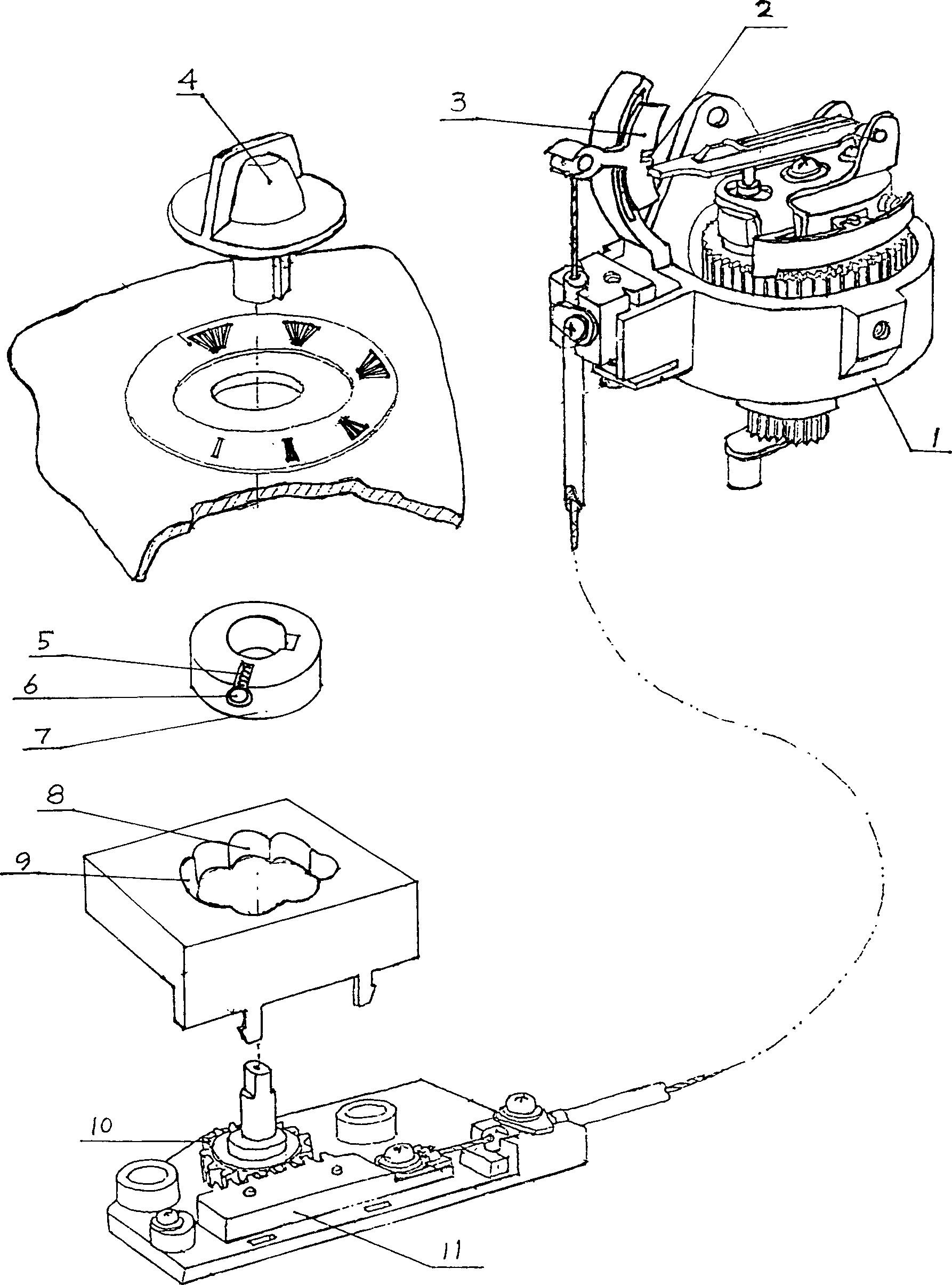
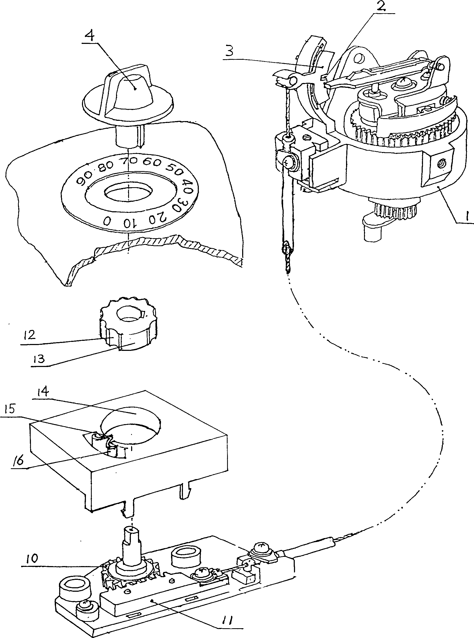
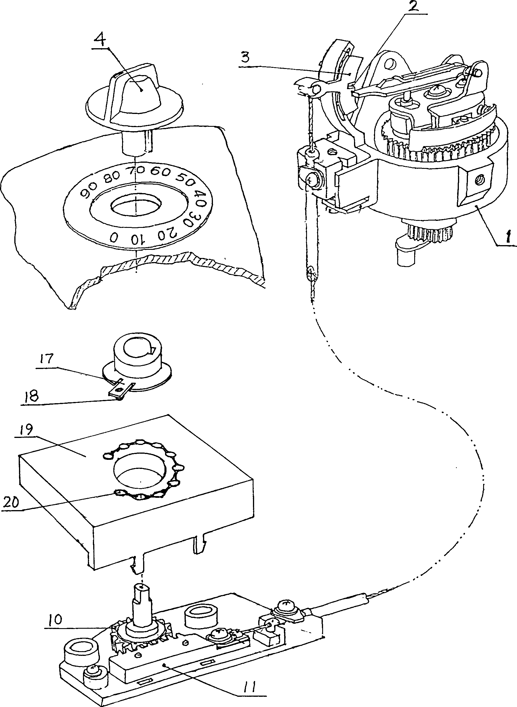
[0008] The present invention will be further described below with embodiment and accompanying drawing:

[0009] figure 1 A preferred embodiment of the invention is shown. The same parts as the electric fan angle adjustment device disclosed in the patent No. 89100824 technology are housed in the housing 1. Between the input angle signal converter composed of the gear 10 and the rack 11 and the baffle plate 3 with the gap 2, the There are the same parts in the electric fan angle adjustment device announced with the patent application number 00117492.4 technology. The difference between this example and the above-mentioned technology is that the angle adjustment button 4 is connected to the input angle signal converter formed by the gear 10 and the rack 11 below the angle adjustment button 4. A segmented positioning mechanism is installed between them. Wherein, an elastic device composed of a spring 5 and a ball 6 is installed in the block surface 7 connected to the angle adjus...


PUM


Abstract

The invention relates to an electric oscillating angle regulator, belong to accessories of electric fan, comprising: an angle modulation knob, a dial, an imported angle signal converter, a stretching wire, a baffle plate with cut, and a segmented positioning device between the angle modulation knob and the imported angle signal converter, which has a plurality of segmented positioning modes, and the minimum distance when segmented position is bigger than the return error and idle displacement of the course that oscillating adjusting the angle modulation knob. Said invention avoids the idle operation when operating the angle modulation knob, to form a quick and effective electric oscillating angle regulator, which fit the oscillating fan.

Description

technical field [0001] The invention relates to an electric fan oscillating angle adjusting device, which is especially suitable for manipulating the angle adjustment knob on the panel of the electric fan seat, so that the electric fan can effectively adjust the swing angle. Background technique [0002] In the prior art, in the patented inventions "Electric Fan Swing Angle Adjustment Device" (ZL89100824) and "Electric Fan Swing Angle Adjustment Device" (Application No. 00117492.4), a user preset swing angle value is shown. , the automatic angle adjustment system that automatically completes the angle adjustment by the electric fan itself, referring to the original text, we can see that the angle adjustment system is composed of a housing, a worm-worm gear-gear reduction mechanism, a variable length crank mechanism of a planetary gear system, a ratchet pawl clutch, a cam- Swing rod sampler, swing rod-push plate ratchet control mechanism, angle adjustment button, dial, input ...

Claims


Application Information

Patent Timeline
IPC IPC(8): F04D27/00
Inventor 蒋亮健
Owner 蒋亮健
Why Eureka
Try Eureka