Methods and apparatus for reconstructing amplitude modulation signals in polar modulation transmitters

a technology of polar modulation transmitter and amplitude modulation signal, which is applied in the direction of modulation, digital transmission, code conversion, etc., can solve the problems of inability to meet communications standards specifications, inability to achieve discrete-time nature of digital modulation signal, and inability to achieve linearity and power efficiency

Inactive Publication Date: 2009-11-26
PANASONIC CORP
View PDF14 Cites 12 Cited by
  • Summary
  • Abstract
  • Description
  • Claims
  • Application Information

AI Technical Summary

Problems solved by technology

Unfortunately, this results in an undesirable trade-off between amplifier linearity and power efficiency.
Although digitally generating and processing modulation signals in a polar modulation transmitter offers a number of benefits, inaccuracies can occur due to the discrete-time nature of the digital modulation signals.
The leaked power can makes it difficult to comply with communications standards specifications such as adjacent channel leakage ratio (ACLR).

Method used


Image

  • Methods and apparatus for reconstructing amplitude modulation signals in polar modulation transmitters
  • Methods and apparatus for reconstructing amplitude modulation signals in polar modulation transmitters
  • Methods and apparatus for reconstructing amplitude modulation signals in polar modulation transmitters

Examples


Embodiment Construction

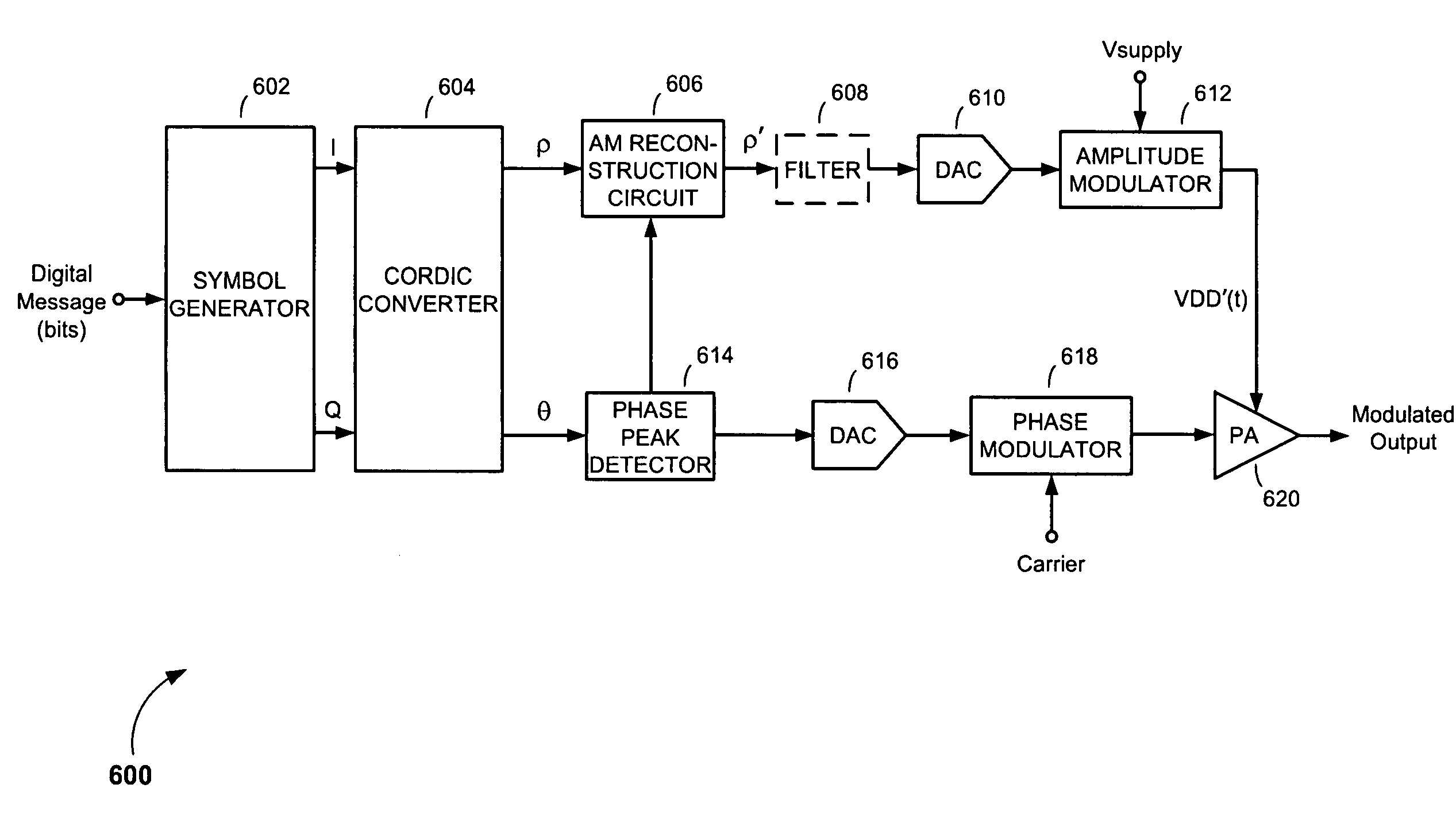
[0022]Referring to FIG. 6, there is shown a drawing of a polar modulation transmitter 600, according to an embodiment of the present invention. The polar modulation transmitter 600 comprises a symbol generator 602, a rectangular-to-polar converter (such as a Coordinate Rotation Digital Computer (CORDIC) converter) 604; an amplitude modulation (AM) path that includes an AM reconstruction circuit 606, optional low-pass filter (LPF) 608, AM path digital-to-analog converter (DAC) 610 and amplitude modulator 612; a phase path that includes a phase peak detector 614, PM path DAC 616 and phase modulator 618; and a power amplifier (PA) 620.

[0023]Similar to the polar modulation transmitter 200 in FIG. 2, the symbol generator 602 of the polar modulation transmitter 600 of the present invention is configured to receive a digital message to be transmitted and generate in-phase (I) and quadrature phase (Q) symbol sequences formatted according to an applicable modulation scheme or standard. The C...


PUM


Abstract

Methods and apparatus for reconstructing discrete-time amplitude modulation signals in polar modulation transmitters. An exemplary polar modulation transmitter includes a symbol generator, a rectangular-to-polar converter, a peak phase detector, and an amplitude modulation reconstruction circuit. The symbol generator generates rectangular-coordinate modulation symbols from which the rectangular-to-polar converter generates an amplitude modulation signal containing discrete-time amplitude samples and an angle modulation signal containing discrete-time angle samples. The peak phase detector circuit detects phase reversals or near phase reversals represented in samples of the angle modulation signal. The amplitude modulation reconstruction circuit responds by reconstructing samples in the amplitude modulation signal that correspond to detected phase reversals or a near phase reversals represented in samples of the angle modulation signal.

Description

FIELD OF THE INVENTION[0001]The present invention relates to processing signals in communications transmitters. More specifically, the present invention relates to methods and apparatus for increasing the accuracy of signals in polar modulation transmitters.BACKGROUND OF THE INVENTION[0002]In an effort to increase spectral efficiency, many state-of-the-art communications systems, including third generation (3G) cellular communications systems such as EDGE (Enhanced Data rates for GSM Evolution) and W-CDMA (Wideband Code Division Multiple Access), employ modulation schemes that produce non-constant-envelope signals. In a traditional quadrature-modulator-based transmitter, the levels of these non-constant-envelope signals are reduced before being introduced to the transmitter's power amplifier (PA), and the PA is configured to operate in its linear region of operation to prevent signal clipping. Unfortunately, this results in an undesirable trade-off between amplifier linearity and po...

Claims


Application Information

Patent Timeline
Patent Type & Authority Applications(United States)
IPC IPC(8): H04B1/02
CPCH04B1/0483H03M1/661
Inventor LEE, WAYNE S.
Owner PANASONIC CORP
Why Eureka
Try Eureka