

Mechanical assembly with incompatible metallic materials
A technology of mechanical components and metals, applied in vehicle parts, fishing, animal husbandry, etc., can solve problems such as electrolytic corrosion, achieve the effect of improving corrosion resistance, reducing thickness and weight
- Summary
- Abstract
- Description
- Claims
- Application Information
AI Technical Summary
Problems solved by technology
Method used
Image

Examples
no. 1 example
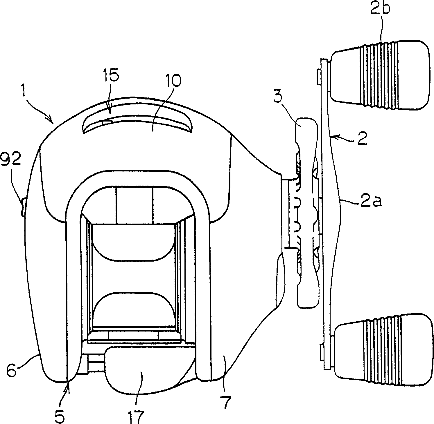
[0054] figure 1 is a top view of a dual-bearing reel according to a first embodiment of the present invention.
[0055] The double bearing reel shown in the figure is a lure throwing reel, which includes a reel body 1; a reel rotating handle 2 placed on the first side of the reel body 1; A wheel 3 is placed on a first side of the reel body 1 adjacent to the handle 2 for adjusting the drag. The handle 2 is a two-handle type, and has a plate such as an arm portion 2a, and handle portions 2b rotatably provided at both ends of the arm portion 2a. The outer edge surface of the arm portion 2a is smooth without joints, providing a structure to prevent tangling of the fishing line.
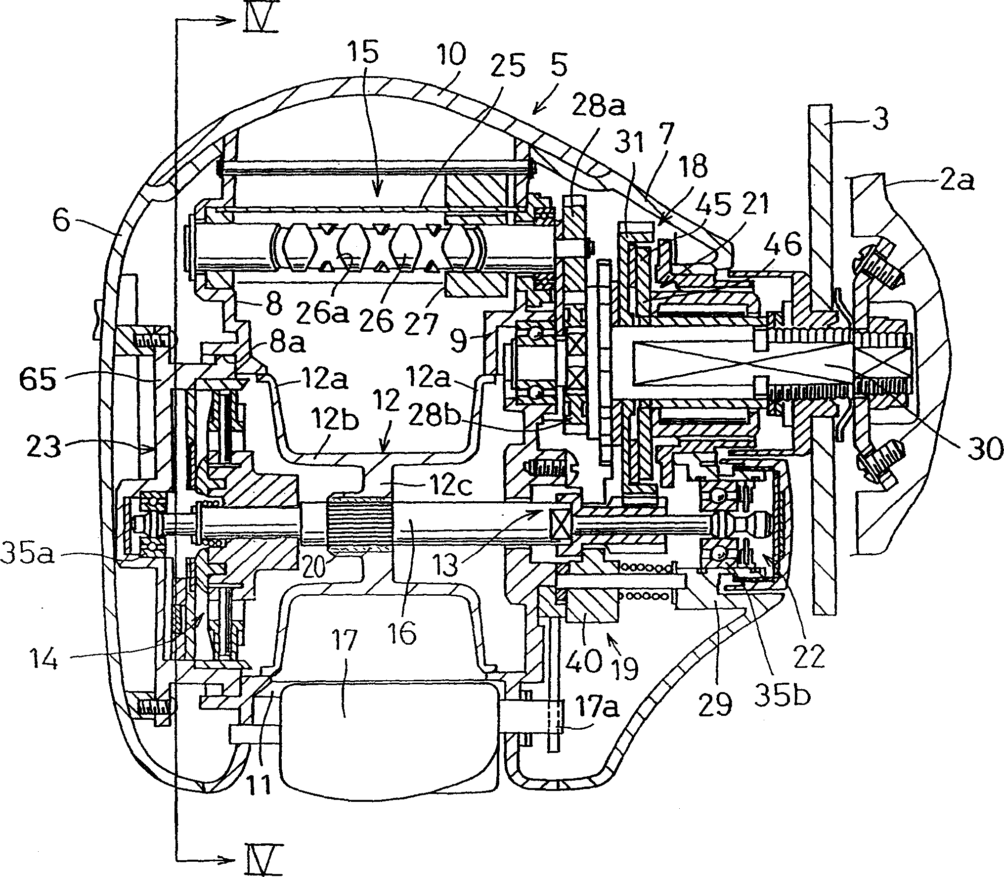
[0056] Such as figure 2 As shown, the reel body 1 comprises a frame 5 made of a magnesium alloy, and first and second side shells 6 and 7 also made of a magnesium alloy. The first and second side shells 6 and 7 are installed on two sides of the frame 5 respectively. The front shell 10 made of magnes...
no. 2 example
[0095] Although in the first embodiment, the invention has been explained with reference to a double bearing reel, the invention can also be applied to a helical reel.
[0096] Figure 8 to Figure 10 , shows a helical reel according to a second embodiment of the present invention. The spiral reel includes a reel main body 102 rotatably supported on a handle 101 , a rotor 103 and a reel 104 . The rotor 104 is rotatably supported on the front side 102 of the reel body. The line reel 104 is configured to respond to the rotation of the rotor 103, and receives the fishing line on its peripheral surface. The winding drum 104 is also arranged to move the front part of the rotor 103 back and forth in the direction of the rotor shaft.
[0097] The reel main body 102 includes a shell portion 110 supporting the rotor 103 and the winding drum 104 , and a movable cover portion 111 contacting the shell portion 110 through screws. Shell portion 110 is a thin component of magnesium alloy,...
no. 3 example
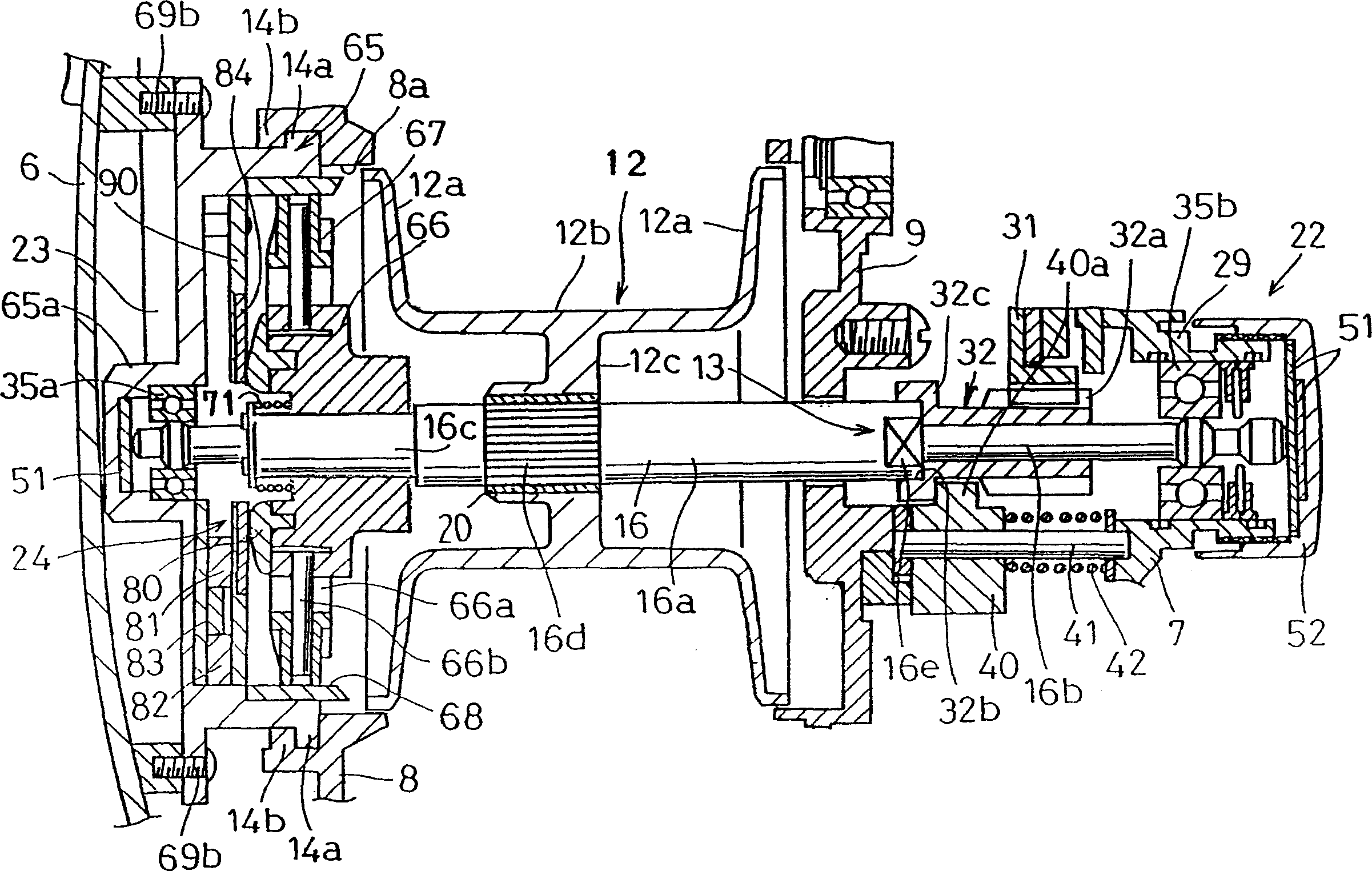
[0116] Figure 11 Here, the reel 12 is a magnesium alloy member obtained by injection molding according to a die-casting molding process. The winding reel 12 has a dish-shaped flange portion 12a on both sides thereof, and a cylindrical wire winding cylinder portion 12b interposed between the two flange portions 12a. The wire winding drum 12 has an integrally formed hollow circular protrusion 12c located on the inner edge side and the axial center portion of the wire winding cylindrical portion 12b. An aluminum alloy sleeve is press-inserted on the inner edge side of the knob 12c. A bushing 20 is integrated in order to prevent electrolytic corrosion of the coil 12 made of magnesium. The winding spool 12 is secured relative to the winding spool 16 via a sleeve 20 by means of serrations, non-rotatably. The fixing method is not limited to the concave-convex zigzag connection, and adhesion, injection molding, etc. can be used.
[0117] Such as Figure 12 As shown, a metal oxid...
PUM
 Abstract
Description
Claims
Application Information