Manufacturing method of small sized turbine shaft

A manufacturing method and turbine shaft technology, which is applied in the direction of blade support components, engine components, machines/engines, etc., can solve the problems that the roughness of the groove cannot be guaranteed, the supercharger rubs, and the sealing groove cannot be ground out, etc.

Inactive Publication Date: 2005-11-09
CHONGQING JIANGJIN SHIPBUILDING IND
View PDF0 Cites 8 Cited by
  • Summary
  • Abstract
  • Description
  • Claims
  • Application Information

AI Technical Summary

Problems solved by technology

[0003] The above-mentioned method for manufacturing the turbine shaft has the following disadvantages: 1. In the traditional process, the seal groove is processed by first turning the seal groove to a certain size, then grinding the end face of the turbine, and then using a shovel machine to shovel the seal groove. We know that the seal groove The groove has a high precision requirement relative to the turbine end face. This will cause the length dimension of the seal groove relative to the turbine end face to become uncertain due to the non-coincidence of the benchmarks after the two machinings and the tolerance of the seal groove relative to the turbine end face. The margins on both sides of the groove are unequal or deviate from the center of the groove, resulting in the seal groove being scrapped because it cannot be ground out. In addition, the speed of the shovel bed is low, and the grain size of the grinding wheel must be selected coarser (if a fine grinding wheel is selected, the grinding temperature of the end face of the groove of the part will be reduced. Rising and dis

Method used


Image

  • Manufacturing method of small sized turbine shaft

Examples


Embodiment Construction

[0010] The specific implementation manners of the present invention will be further described below in conjunction with the accompanying drawings.

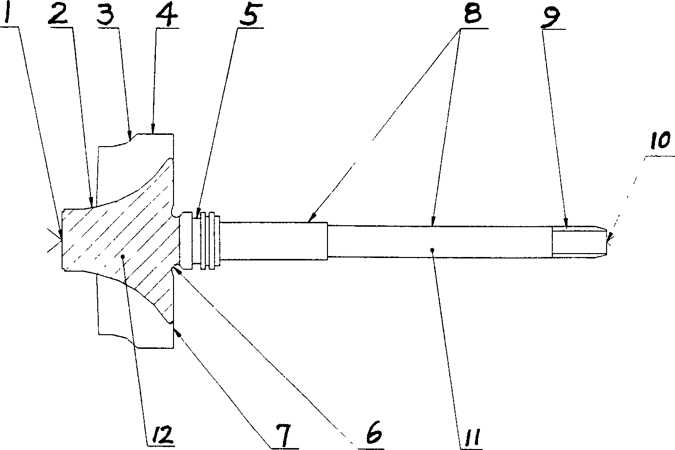
[0011] see figure 1 , the manufacture method of a kind of small-sized turbine shaft of the present invention, comprises: (1), turbine 12 and shaft 11 are welded as a whole with friction welding; (2), heat treatment is to eliminate stress; (3), sanding welding place; ( 4), carry out the tensile test; (5), use the clamping ring for the turbine shaft and the three claws to clamp the large outer circle 4 of the turbine, align the end face 7 of the turbine, first turn the welding scar, and then turn the shaft 11 to the required length. Drill the center hole 10 at the shaft end; (6), use the three claws to clamp the top cone surface of the vortex end 2, use the top center hole 10, rough turn each outer circle 4, 8, and turn the R groove 6 to the required size; (7) , color flaw detection; (8), grinding the center hole 1, 10; (9), grindi...


PUM


Abstract

This invention is a small type turbine axis manufacturing method. The turbine is welded with axis; stress is eliminated through heat treating. Weld zone is sanded, then tension test is done. Burr is done first and then axis is processed t needed length, and central hole is punched at end of axis. Outer circle and R slot are processed to needed dimension, then liquid penetrant test, Central hole and turbine outer circle are grinded, then turbine end face is processed to needed dimension, then each outer circle is processed to needed dimension. Penetration testing and high frequency hardening and alignment are done. Stress is eliminated through heat treating and central hole is grinded, turbine end face is grinded to needed dimension, then each outer circle on the axis is grinded. Screw thread is roll extruded, turbine outer circle is precise grinded. Turbine end face is grinded, then each outer circle on the axis is precise grinded, sealing slot is grinded, turbine meridian plane is grinded, burr is eliminated, then dynamic balancing experiment is done for testing.

Description

technical field [0001] The invention relates to a process method for machining a turbine shaft of a supercharger. In particular, it relates to a method of manufacturing small turbine shafts. Background technique [0002] There are 20 processes in the traditional turbine shaft processing, which are as follows: 1. Electron beam welding is used to weld the turbine and shaft together; 2. Heat treatment to eliminate stress; 3. Sanding the weld; 4. Tensile test; 5. Coloring Flaw detection; 6. Use the clamping ring and three claws to clamp the large outer circle of the turbine shaft, align the A surface of the turbine, turn the shaft to the required length, punch the center hole at the end of the shaft, and use the top center hole to roughly turn each The outer circle reaches the required size, then turn around and clamp, align the outer circle of B, polish the end face, and drill the center hole of the turbine end; 7, grind the center hole; 8, first turn the end face of the turbi...

Claims


Application Information

Patent Timeline
IPC IPC(8): F01D5/02
Inventor 段昌文牟玉玲向理高
Owner CHONGQING JIANGJIN SHIPBUILDING IND
Why Eureka
Try Eureka