Integral permanent-magnet bistable micro electromagnet driver

A bistable, micro-electromagnetic technology, applied in the direction of non-polar relays, circuits, magnets, etc., can solve problems such as power consumption in the state maintenance stage that is difficult to solve, and achieve the effect of state switching and maintenance

Active Publication Date: 2005-11-09
SHANGHAI JIAO TONG UNIV
View PDF0 Cites 6 Cited by
  • Summary
  • Abstract
  • Description
  • Claims
  • Application Information

AI Technical Summary

Problems solved by technology

[0003] Through the retrieval of prior art documents, it is found that Lionet HouLet et al. wrote the article "Movable Vertical Mirror Arrays for Optical Microswitch Matrixes and Their Electromagnetic Actuation", the micro-electromagnetic actuator array introduced in this article adopts SU-8 thick glue process to make electroformed micro-coils and soft A mask of magnetic material, this design realizes the integrated manufacturing of the micro-electromagnetic driver array, but it is difficult to solve the power consumption problem in the state maintenance stage because the bistable mechanism is not introduced

Method used


Image

  • Integral permanent-magnet bistable micro electromagnet driver

Examples


Embodiment Construction

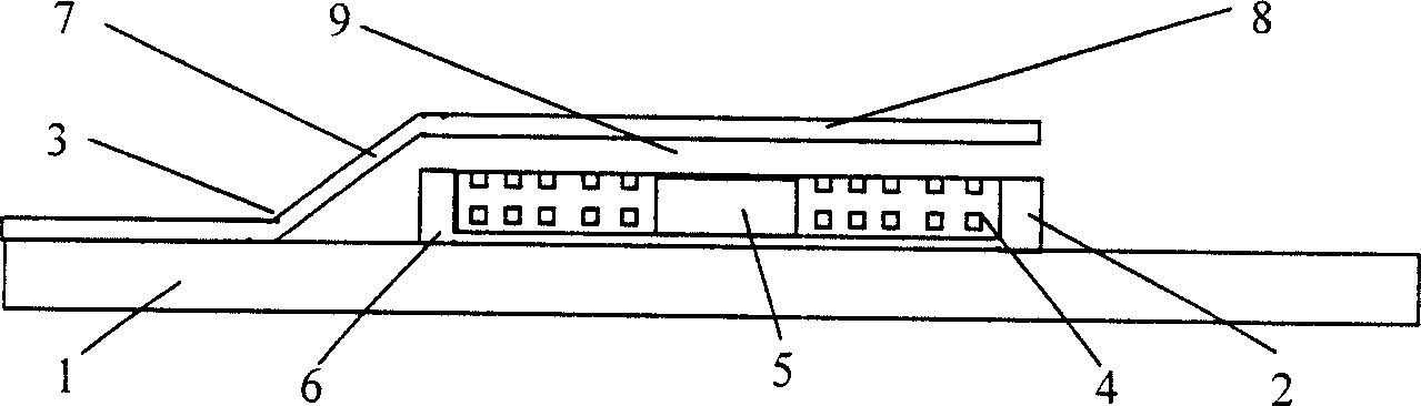
[0014] Such as figure 1 As shown, the present invention includes: a substrate 1, a stator 2, and a mover 3, and the stator 2 includes: a micro-drive coil winding 4, a permanent magnet 5, a soft magnetic yoke 6, and the permanent magnet 5 is located at the micro-drive coil winding 4 In the center, the soft magnetic yoke 6 is located below and around the micro-drive coil winding 4 , the soft magnetic yoke 6 is located below the permanent magnet 5 , and the stator 2 and the mover 3 are fixed on the substrate 1 .

[0015] The micro drive coil winding 4, the central permanent magnet 5 and the soft magnetic yoke 6 are integrated together.

[0016] The mover 3 includes: a micro-cantilever beam 7 and a soft magnetic armature 8 , the soft magnetic armature 8 is fixed above the soft magnetic yoke 6 and the permanent magnet 5 through the micro-cantilever beam 7 on the substrate 1 .

[0017] There is an air gap 9 between the soft magnetic yoke 6 , the permanent magnet 5 and the soft magn...


PUM


Abstract

The invention discloses an integral permanent magnetism bi-stable microelectromagnetic driver, it includes: The substrate, the stator, rotor the stator includes: Micro drive coil winding, permanent magnet, the soft magnetism magnetic yoke, the permanent magnet which locates in the micro drive coil winding, the soft magnetism magnetic yoke which is lower and around the micro drive coil winding, the soft magnetism magnetic yoke which under the permanent magnet, the stator and rotor are fixed on the substrate.

Description

technical field [0001] The invention relates to a driver, in particular to an integrated permanent magnet bistable micro-electromagnetic driver, which belongs to the technical field of precision machinery. Background technique [0002] Devices such as optical switches, micro-relays and radio frequency switches based on MEMS technology are the basic key devices used in future all-optical communication networks, advanced instrumentation and control systems, phased array radar and mobile communications. Such devices usually work in the on and off state, the driving stroke is 10 microns to 100 microns, the driving force is in the order of millinewtons, and the response time is in the order of milliseconds to microseconds, requiring low power consumption. Electrostatic drive is difficult to meet the above requirements due to high working voltage, small driving force and output stroke. Micro-electromagnetic drive is expected to fundamentally overcome the above shortcomings, but i...

Claims


Application Information

Patent Timeline
Patent Type & Authority Applications(China)
IPC IPC(8): H01F7/122
Inventor 戴旭涵赵小林丁桂甫汪红蔡炳初
Owner SHANGHAI JIAO TONG UNIV
Why Eureka
Try Eureka