
Method for manufacturing an optical fiber preform by MCVD

A chemical vapor deposition, preform technology, applied in glass manufacturing equipment, manufacturing tools, metal processing equipment and other directions, can solve the problem of no disclosure, and achieve the phenomenon of reducing or decreasing the refractive index, improving bandwidth, and improving optical properties. Effect

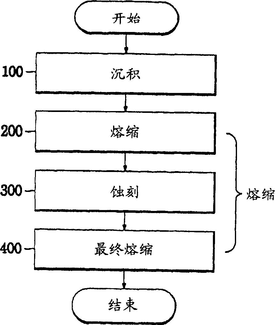
Inactive Publication Date: 2005-11-09
LG CABLE INC
View PDF4 Cites 2 Cited by
  • Summary
  • Abstract
  • Description
  • Claims
  • Application Information

AI Technical Summary

Problems solved by technology

[0016] However, this patent does not disclose a method of optimizing the inner diameter of the tube by simultaneous etching and shrinkage prior to the sealing step, thereby reducing the GeO generated in the sealing step due to the increase in the inner diameter of the tube during the etching step. 2 incidental volatile

Method used


Image

  • Method for manufacturing an optical fiber preform by MCVD
  • Method for manufacturing an optical fiber preform by MCVD
  • Method for manufacturing an optical fiber preform by MCVD

Examples


Embodiment Construction

[0035] Hereinafter, preferred embodiments of the present invention will be described in detail with reference to the accompanying drawings.

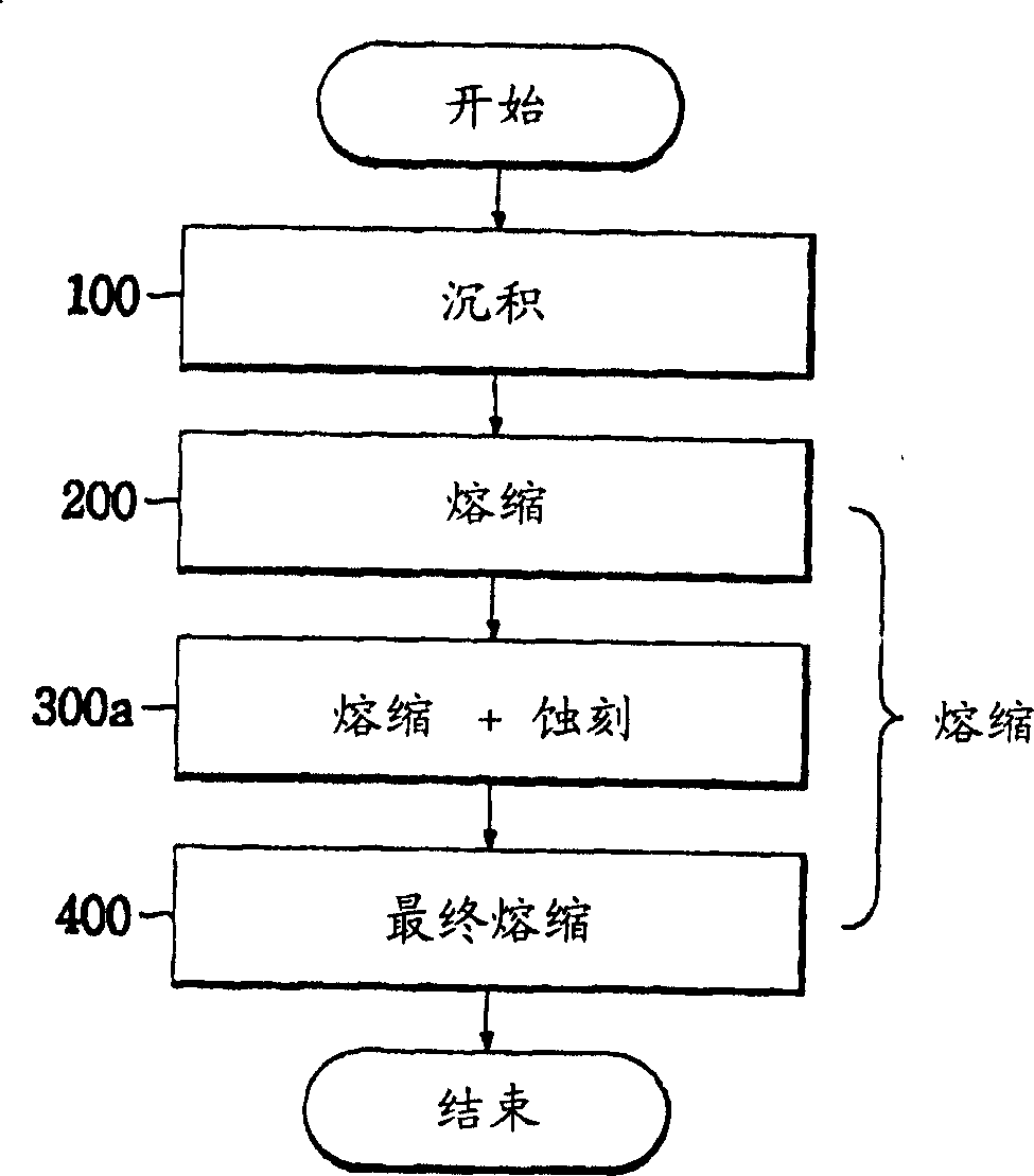
[0036] first, Figure 1b is a flow chart illustrating the method for preparing an optical fiber preform by MCVD (modified chemical vapor deposition) of the present invention;

[0037] refer to Figure 1b , The method for manufacturing an optical fiber preform according to the present invention includes: a deposition step 100 , a shrinkage step 200 , a shrinkage / etching step 300 a and a sealing step 400 .

[0038] Hereinafter, a method for manufacturing an optical fiber preform according to the present invention will be explained step by step with reference to the accompanying drawings.

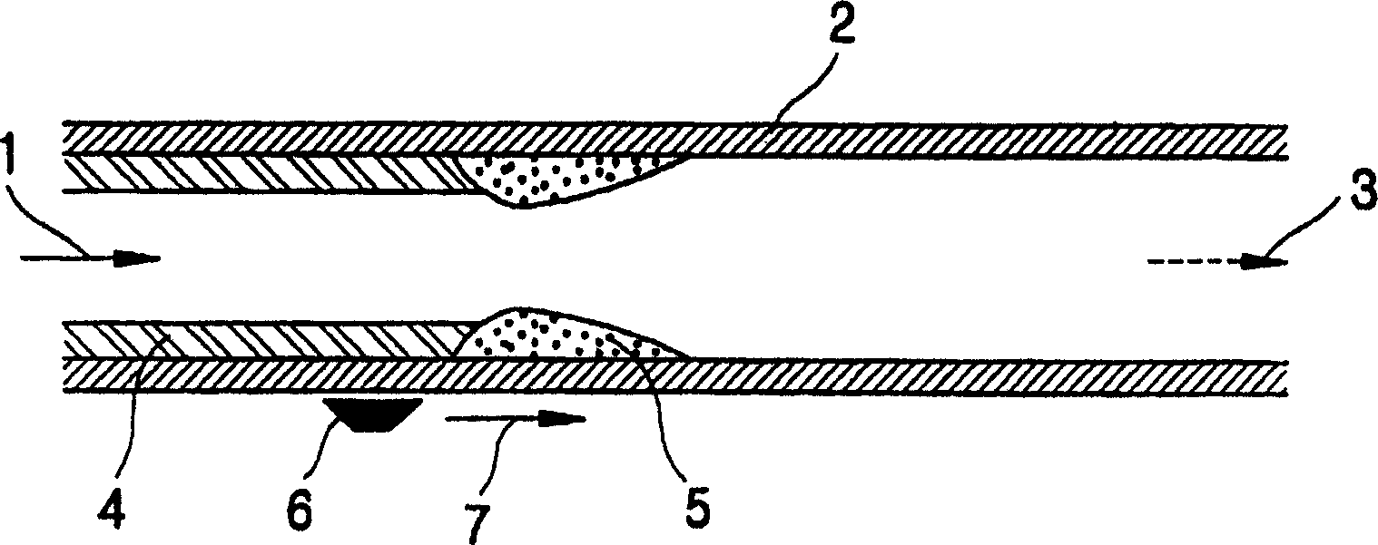
[0039] 1. Deposition step (see figure 2 )

[0040] like figure 2 As shown, in the deposition step, reactant gas 1 such as SiCl 4 、GeCl 4 , POCl 3 , He and O 2 Inject quartz tube 2. Then, the outside of the quartz tube 2 is heated with the tor...


PUM


Abstract

Disclosed is a method for manufacturing an optical fiber preform in MCVD, which simultaneously performs an etching process for injecting a reaction gas for etching into a tube and a collapsing process for heating and collapsing the tube in order to minimize or eliminate an index dip existing at the center of the preform core. By using this method, the index dip phenomenon of the optical fiber preform can be minimized or eliminated, so it is possible to make an optical fiber having improved optical characteristics, particularly having improvement in a bandwidth and a polarization mode dispersion (PMD).

Description

technical field [0001] The present invention relates to methods for preparing optical fiber preforms using modified chemical vapor deposition (MCVD), and more particularly to methods for preparing optical fibers with improved optical properties by eliminating index dips produced during processing steps method. In particular, by employing this method, multimode optical fibers capable of transmitting gigabits can be prepared without other auxiliary materials. Background technique [0002] Figure 1a is a flow chart showing a method for preparing an optical fiber preform according to conventional MCVD. [0003] In general, an optical fiber preform is prepared by a deposition step 100 and a shrinkage step 200-400. More specifically, the shrinking step includes a shrinking step 200 , an etching step 300 and a sealing step 400 . [0004] As known to those skilled in the art, methods for preparing optical fiber preforms can be classified into external deposition methods and inte...

Claims


Application Information

Patent Timeline
IPC IPC(8): C03B37/018
CPCB24B3/003B24B27/0076
Inventor 洪春根姜秉润李东旭姜秉哲
Owner LG CABLE INC
Learn More