Elevator control apparatus
A technology for elevator control devices and power storage devices, which is applied in the direction of circuit devices, battery circuit devices, elevators in buildings, etc., can solve problems such as share consumption, and achieve the effect of eliminating useless power consumption and reducing standby power
- Summary
- Abstract
- Description
- Claims
- Application Information
AI Technical Summary
Problems solved by technology
Method used
Image


Examples
Embodiment approach 1
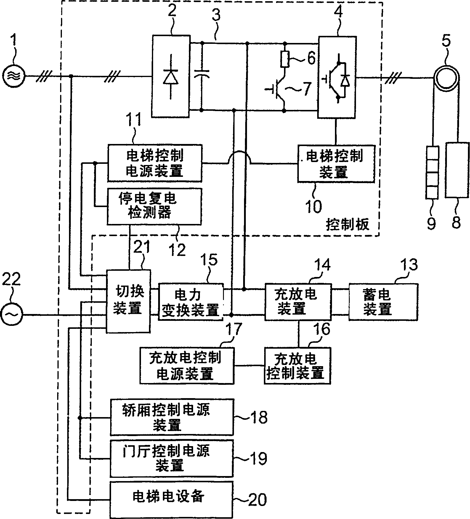
[0026] figure 1 It is a block diagram showing the configuration of the elevator control device according to Embodiment 1 of the present invention, and is an example of the system configuration for fully automatic operation of the elevator even during a power failure. The control board for controlling the elevator has a converter 2 composed of diodes and the like that converts the AC power output by the commercial frequency power supply 1 for the three-phase AC power into DC power, and the capacitor and the regenerative resistor 6 that pass through the DC bus 3 and The regenerative resistance control circuit 7 composed of transistors supplies the inverter 4 that converts the direct current converted by the converter 2 into alternating current with variable voltage and frequency, and the alternating current from the inverter 4 is supplied to the motor that drives the winch 6 in rotation. By rotationally driving the hoist 5, the car 8 and the balance weight 9 connected to both en...
Embodiment approach 2
[0038] In an energy-saving elevator that uses a power storage device such as a secondary battery as an elevator control device, a large amount of power is required to control the added power storage device. Usually, the electric power required for the elevator to stand by is sufficient only to answer calls from the hall, and therefore there is a problem that at least a share of the electric power required by the added power storage device is wasted. This second embodiment establishes a system that can suppress wasteful power consumption even if a power storage device is added to the control board.
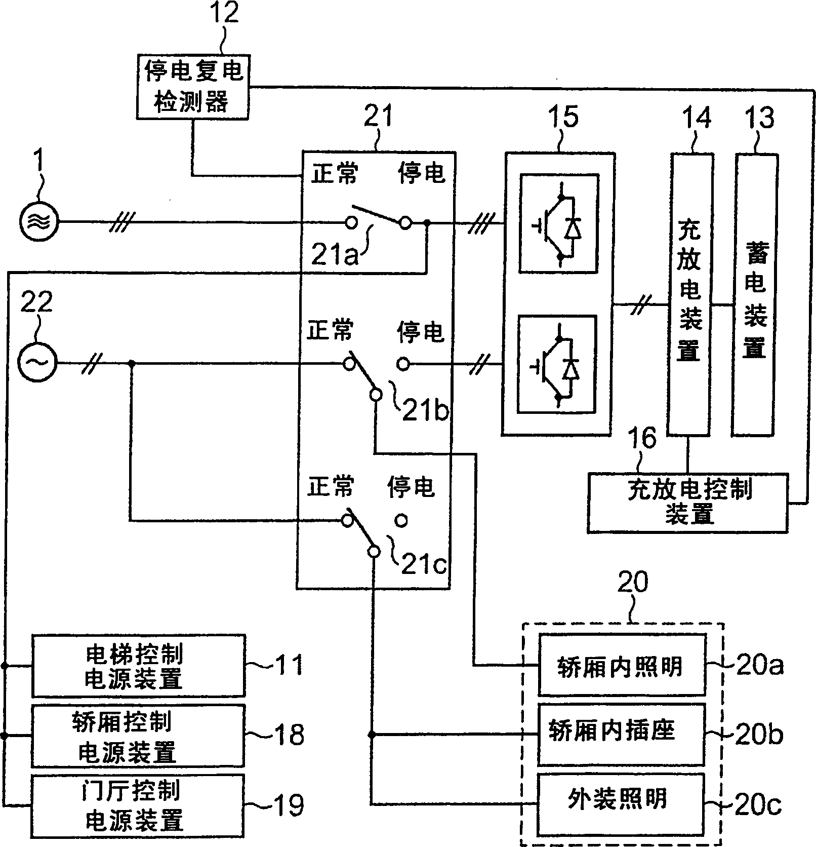
[0039] image 3 It is a block diagram showing the configuration of the elevator control device according to Embodiment 2 of the present invention. image 3 In the shown embodiment 2, with figure 1 Parts of the system according to Embodiment 1 shown are denoted by system symbols, and description thereof will be omitted. image 3 In the shown embodiment 2, with respect to embodime...
Embodiment approach 3
[0047] Figure 7 It is a block diagram showing the configuration of an elevator control device according to Embodiment 3 of the present invention. Figure 7 In the illustrated embodiment 3, with image 3 The shown embodiment 2 is the same, the elevator control device 10 in the control panel is provided with a standby state identification device 10A, and at the same time, the charge and discharge control power supply device of the charge and discharge control device 16 of the power storage device 13 is connected with the elevator control device at the control panel side. The power supply unit 11 is shared.
[0048] This constitutes a common control power supply device, which can save space for the equipment. Therefore, the charge and discharge control power regulator 26 is provided so that the power supplied to the charge and discharge control device 16 can be controlled. This charge and discharge control power regulator 26 releases, for example, the contact 26a according to...
PUM
 Abstract
Description
Claims
Application Information