Light-emitting display

A light-emitting display and capacitor technology, applied in static indicators, electroluminescent light sources, instruments, etc., can solve the problem that organic light-emitting displays cannot display images correctly

Active Publication Date: 2005-11-23
SAMSUNG DISPLAY CO LTD
View PDF0 Cites 27 Cited by
  • Summary
  • Abstract
  • Description
  • Claims
  • Application Information

AI Technical Summary

Problems solved by technology

Thus, the organic light emitting display may not display images correctly beca

Method used


Image

  • Light-emitting display
  • Light-emitting display
  • Light-emitting display

Examples


Embodiment Construction

[0026] Exemplary embodiments of the invention are shown and described in the following detailed description, in a manner that is merely illustrative of the best mode contemplated by the inventors for carrying out the invention. As will be realized, the invention is capable of modifications in several obvious respects, all without departing from the invention. Accordingly, the drawings and description are illustrative in nature and not restrictive. In order to make the present invention clearer, parts that are not described in this specification are omitted, and parts that are provided with similar descriptions have the same reference numerals.

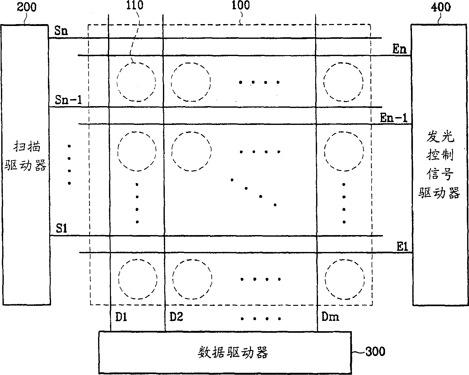
[0027] figure 2 The configuration of the organic light emitting display according to the first exemplary embodiment of the present invention is shown.

[0028] refer to figure 2 , the organic light emitting display may include an organic light emitting display panel 100 , a scan driver 200 , a data driver 300 , and a light emittin...


PUM


Abstract

A pixel circuit of a light-emitting display that reduces the influence of kickback generated by parasitic capacitance. The pixel circuit includes first to fourth transistors, a capacitor, and a light-emitting element. The first and second transistors are serially coupled to each other and turned on in response to a first control signal. The capacitor is coupled in parallel with the first and second transistors. The third transistor supplies a data voltage to a first electrode of the capacitor in response to a select signal. The fourth transistor outputs a current corresponding to its gate-source voltage, which is based on the voltage of the capacitor. The light-emitting element emits light corresponding to the current from the fourth transistor.

Description

technical field [0001] The present invention relates to a light-emitting display, in particular to an organic light-emitting display using organic materials to emit light. Background technique [0002] Organic light emitting displays generally emit light using organic light emitting elements that emit light using organic materials. The NxM organic light emitting cells arranged in a matrix form can be driven using voltage or current to display images. Since the organic light emitting unit has diode characteristics, it may also be called an organic LED (light emitting diode), which may include an anode (ITO), an organic thin film, and a cathode (metal). The organic thin film may have a multilayer structure including an emission layer (EML), an electron transport layer (ETL), and a hole transport layer (HTL) for balancing electrons and holes to improve luminous efficiency. The organic thin film may further include an electron injection layer (EIL) and a hole injection layer (...

Claims


Application Information

Patent Timeline
IPC IPC(8): G09G3/30G09G3/32
CPCG06F2213/0042G11B31/02G11B33/025G11B33/1493G11B2020/00057
Inventor 严基明郭源奎吴春烈
Owner SAMSUNG DISPLAY CO LTD
Why Eureka
Try Eureka