
Fresnel lens sheet, transmission screen and back projection display unit

A Fresnel lens and lens sheet technology, which is applied in the direction of lenses, projectors with built-in screens/external screens, projection devices, etc. The effect of improving contrast, increasing transmittance, and suppressing reflection

Inactive Publication Date: 2005-11-23
DAI NIPPON PRINTING CO LTD
View PDF2 Cites 7 Cited by
  • Summary
  • Abstract
  • Description
  • Claims
  • Application Information

AI Technical Summary

Problems solved by technology

[0006] However, in the method described in the above-mentioned Patent Document 2, it is necessary to form a light absorbing portion on the light emitting side surface of the Fresnel lens sheet, on the region where the incident light from the light incident side of the base does not pass, so it is necessary for the base to enter. Alignment of the prism element on the light side and the light absorbing part on the light output side
Here, since the lens pitch of the prism element on the light incident side is usually about 0.1 mm, the alignment accuracy must be about 0.01 mm or higher, which is very difficult in manufacturing
In addition, if the prism element group extends in a straight line, you only need to align a single direction perpendicular to the line on the basis of matching the slope of the line; however, if the prism element group extends in an arc shape, you must Alignment is performed in both directions of straight travel, making alignment more difficult
[0007] Moreover, if the alignment accuracy of the prism elements on the light incident side of the base and the light absorbing part on the light exit side is poor, no matter whether the prism element group extends in a straight line or in an arc shape, moiré interference will occur due to alignment errors

Method used


Image

  • Fresnel lens sheet, transmission screen and back projection display unit
  • Fresnel lens sheet, transmission screen and back projection display unit
  • Fresnel lens sheet, transmission screen and back projection display unit

Examples


Embodiment

[0085] Specific examples of the above-mentioned embodiment will be described below.

[0086] (Example)

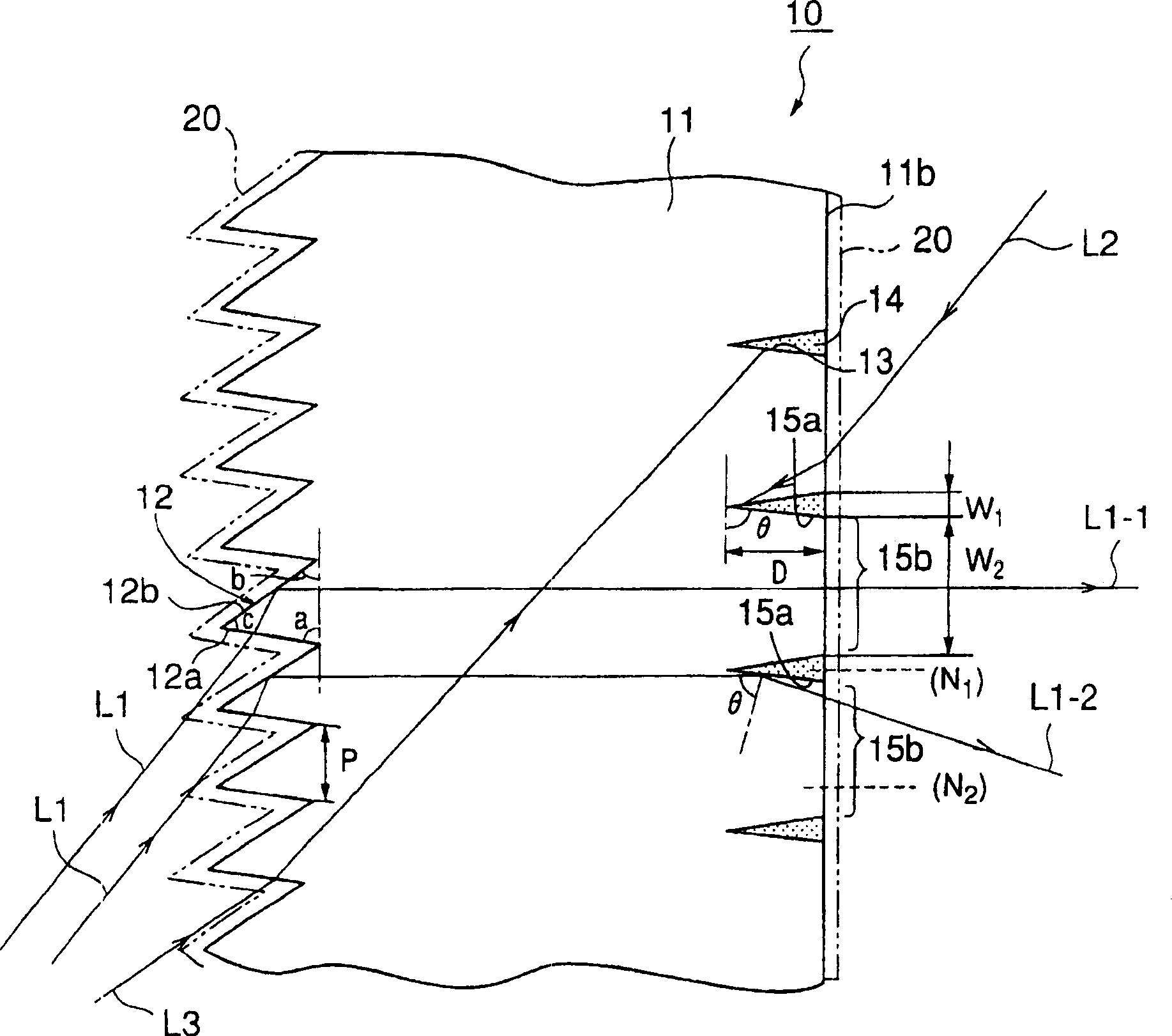
[0087] First, using a mold having a complementary shape corresponding to the shape of the prism element and the shape of the groove, a transparent polycarbonate resin (refractive index 1.59) is stamped to form a prism element and The base of the V-shaped groove.

[0088] The base formed here was planar with a width of 1016 mm, a longitudinal length of 762 mm and a thickness of 4 mm. In addition, the prism apex angle (c) of the prism element on the light incident side of the base is fixed at 38 degrees, and the angle (a) of the refraction surface and the angle (b) of the total reflection surface of each prism element are determined according to the incident angle of light (35~ 71 degrees) and change. Also, the lens pitch (p) of the prism element was 0.11 mm. The groove on the light-emitting side of the base corresponds to the shape of the wedge-shaped light-absorbing par...


PUM


Abstract

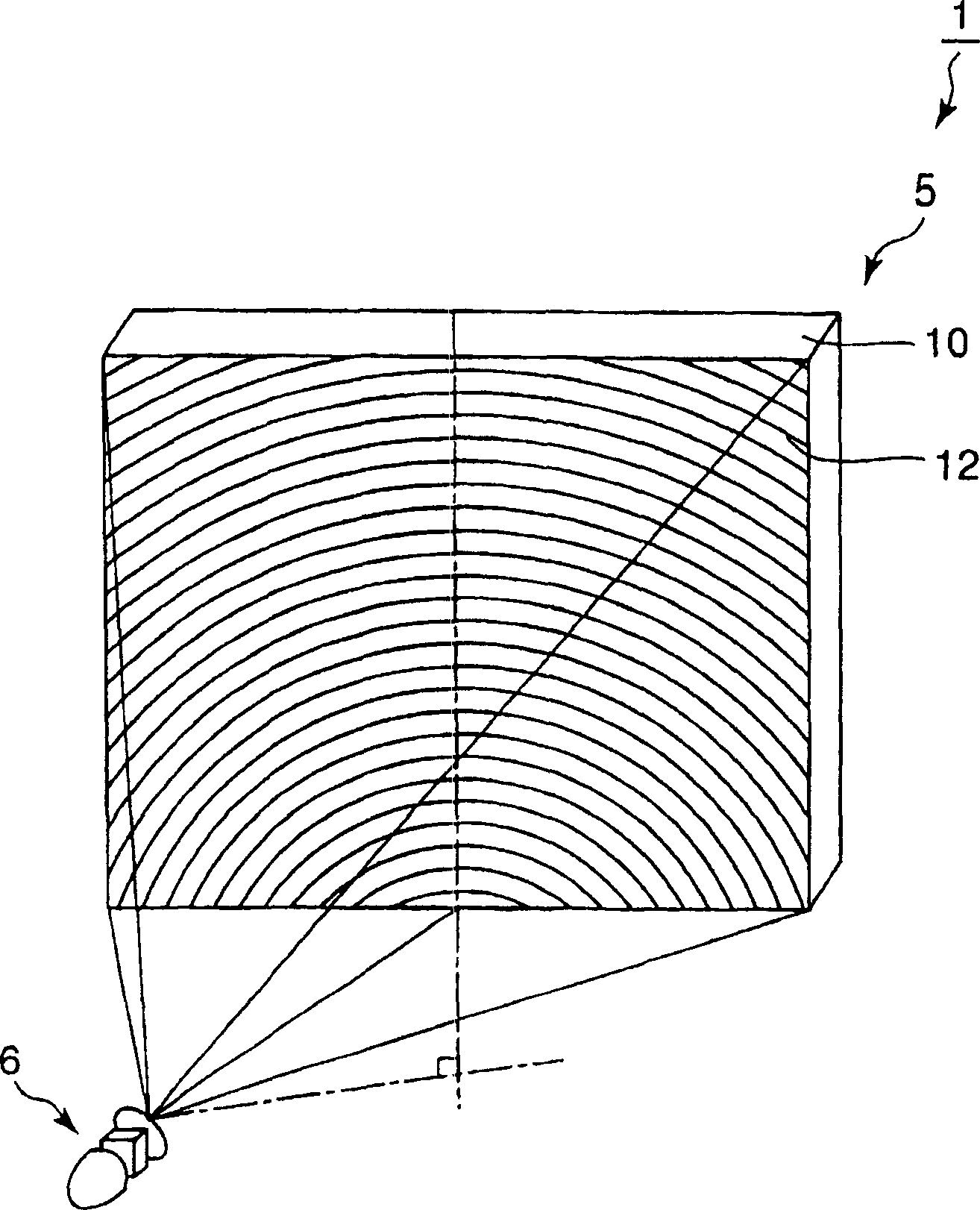
There is provided a Fresnel lens sheet for converging light rays fallen thereon from oblique directions, and capable of reducing the reflection of external light, of enabling displaying images in satisfactory contrast, of suppressing the occurrence of moire and of being easily manufactured. The Fresnel lens sheet 10 includes: a flat base part 11; a plurality of prisms 12 formed on the entrance surface of the base part 11, a plurality of V grooves 13 formed in the exit surface of the base part 11, and a plurality of wedge-shaped light absorbing parts 14 embedded in the V grooves 13, respectively. Each prism 12 has a refraction facet 12a that refracts light rays fallen thereon and a total-reflection facet 12b that totally reflects light rays fallen thereon. The prisms 12 refract and reflect light rays L1 incident thereon at large incident angles to deflect the light rays L1 for travel in a direction substantially perpendicular to the base part 11. The light absorbing parts 14 have a refractive index lower than that of the base part 11. The inclined surfaces 15a, contiguous with the base part 11, of the light absorbing parts 14 embedded in the grooves 13 of the base part 11 reflect the light rays L1 traveling through the base part 11.

Description

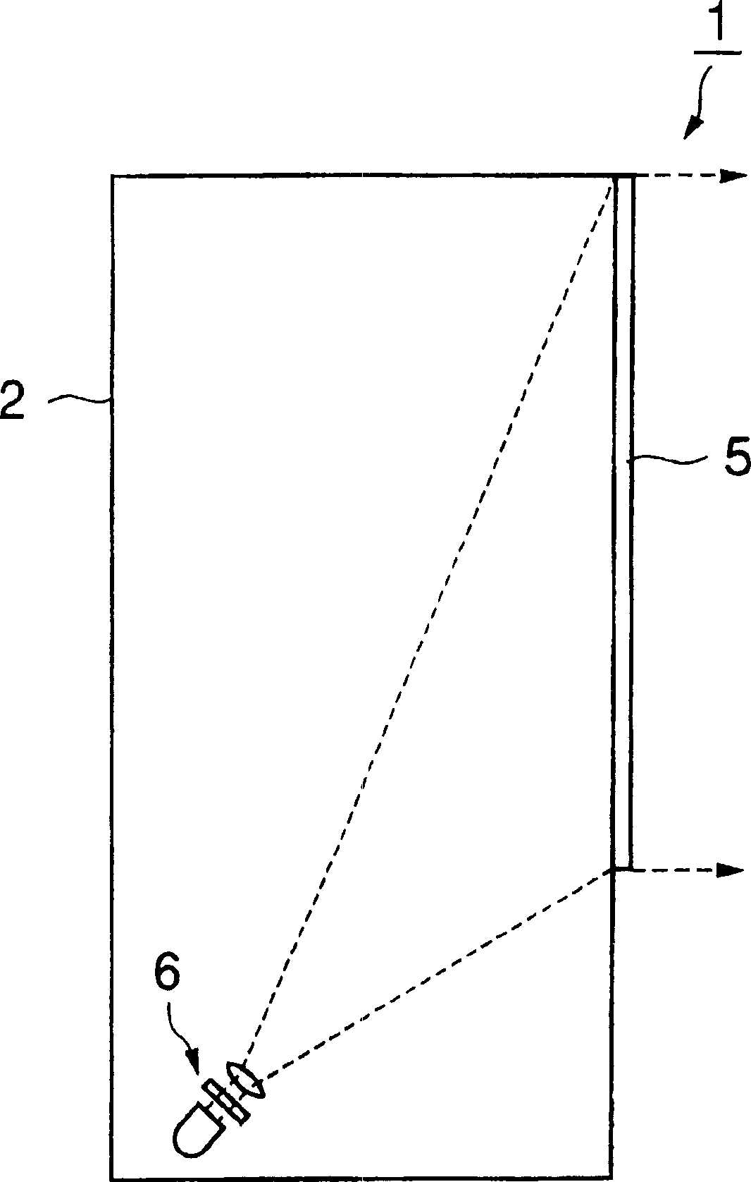
technical field [0001] The present invention relates to a rear projection display device, in particular to a Fresnel lens sheet suitable for projecting image light emitted from a projection device on a transmissive screen from an oblique direction, and a Fresnel lens sheet provided with the Fresnel lens sheet. Lens sheet transmissive screen and rear projection display. Background technique [0002] Japanese Patent Laid-Open No. 61-208041 (Patent Document 1) proposes: in a rear projection display device that projects image light emitted from a projection device on a transmissive screen from an oblique direction, as a method for converging image light from an oblique direction The optical device for the light incident on the transmissive screen uses a prism element group with a triangular cross-section on the light-incident side surface, which can refract the incident light through the first surface of the prism element and be totally reflected by the sec...

Claims


Application Information

Patent Timeline
Patent Type & Authority Applications(China)
IPC IPC(8): G02B3/06G02B3/08G03B21/10G03B21/62G03B21/625
CPCG03B21/625G02B3/06G02B3/08G03B21/62
Inventor 关口博后藤正浩
Owner DAI NIPPON PRINTING CO LTD
Learn More