Expansion valve control method for multiple type airconditioner

A control method and technology for air conditioners, applied in refrigerators, heating and ventilation control systems, compressors, etc., to solve problems such as inaccessibility, inability to exert capacity, and large load changes

Inactive Publication Date: 2005-12-07
PANASONIC CORP
View PDF1 Cites 30 Cited by
  • Summary
  • Abstract
  • Description
  • Claims
  • Application Information

AI Technical Summary

Problems solved by technology

On the contrary, if the correction pulse value is reduced once, the refrigeration cycle is stable, but it is difficult to approach the target superheat degree, and there is a problem that a given capability cannot be exhibited.
[0005] In addition, the opening degree of the expansion valve is controlled by PI to solve the above-mentioned problems. However, when the multi-mode function is used and the operation is performed with more than two chambers, the load fluctuation is large, and there is a limit to the optimization of the refrigeration cycle by such control.

Method used


Image

  • Expansion valve control method for multiple type airconditioner
  • Expansion valve control method for multiple type airconditioner
  • Expansion valve control method for multiple type airconditioner

Examples


Embodiment 1

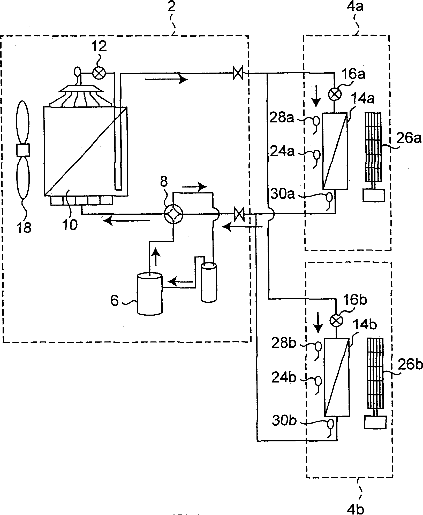
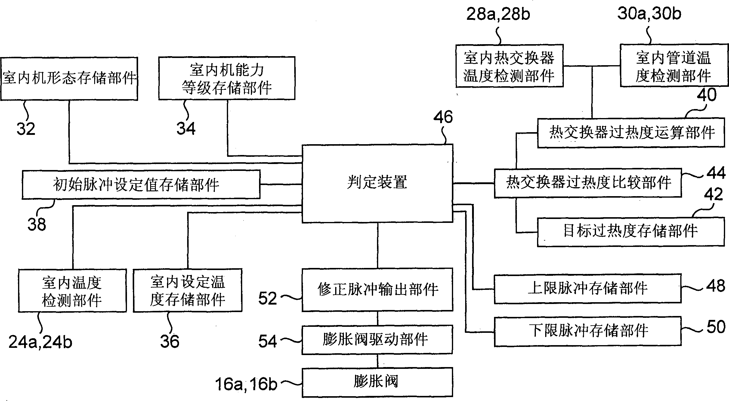
[0021] figure 2 A block diagram showing expansion valve control of each indoor unit 4a, 4b of the multi-system air conditioner according to Embodiment 1 of the present invention.

[0022] Such as figure 2 As shown, each indoor unit 4a, 4b has: an indoor unit form storage unit 32 for storing indoor unit forms such as wall-mounted, roof embedded, and ducted; an indoor unit capacity level storage unit 34 for storing the capacity level of the indoor units 4a, 4b ; An indoor set temperature storage unit 36 ​​that stores an indoor set temperature set by an operation mode setting circuit (not shown) such as a remote controller. According to the indoor unit form stored in the indoor unit form storage part 32 and the capacity level stored in the indoor unit capacity level storage part 34, in addition according to the temperature detected by the indoor temperature detection parts 24a, 24b and the indoor set temperature storage part 36 A plurality of initial pulse set values ​​determ...

Embodiment 2

[0036] Figure 5 A block diagram showing a multi-system air conditioner according to Embodiment 2 of the present invention. exist figure 2 On the basis of the multi-mode air conditioner of the illustrated embodiment, a compressor frequency detection unit 56 for detecting the operating frequency of the compressor 6 is provided, and the compressor frequency detection unit 56 is connected to the determination devices of the indoor units 4a, 4b.

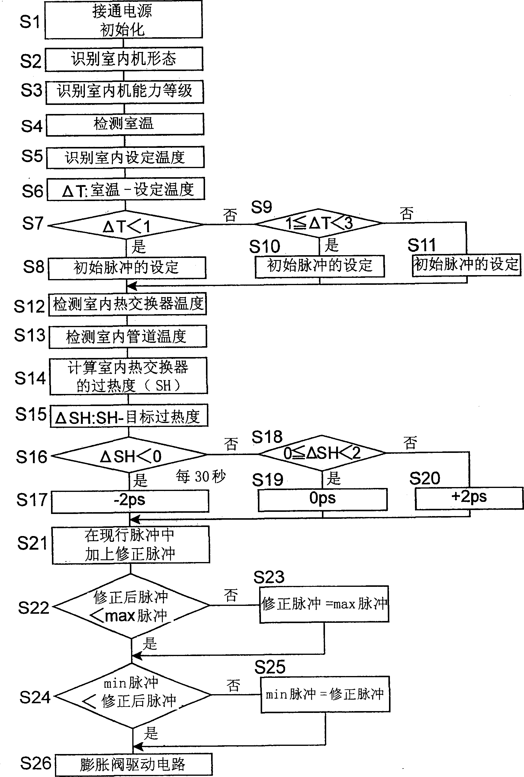
[0037] also, Figure 6 and Figure 7 It is a program flow chart and time chart showing the expansion valve control of the multi-system air conditioner of the second embodiment, and only the differences from the expansion valve control of the first embodiment will be described below.

[0038] Same as Embodiment 1, in this Embodiment 2, after executing step S1 to step S24 or S25, as Figure 6 As shown, it transfers to step S26, and in step S26 it is determined whether an initial pulse signal is received from the outdoor unit 2. That ...


PUM


Abstract

During a cooling or dehumidifying operation, the initial pulse of an expansion valve is set according to the difference between an indoor temperature and an indoor temperature setting, a refrigerant degree of superheat is calculated from an indoor heat-exchanger temperature and a refrigerant outlet temperature, a positive, zero or negative correction pulse is set according to the difference between a calculated refrigerant degree of superheat and a target refrigerant degree of superheat, and the opening of an indoor expansion valve is controlled according to a corrected pulse obtained by adding a correction pulse to the initial pulse. Later, a correction pulse is repeatedly set at specified intervals, upper-limit and lower-limit pulses are set, and a corrected pulse is set appropriately to the upper-limit pulse or the lower-limit pulse when a corrected pulse is higher than the upper-limit pulse or lower than the lower-limit pulse.

Description

technical field [0001] The invention relates to an expansion valve control method of a multi-standard air conditioner in which multiple indoor units are connected to one outdoor unit. Background technique [0002] In the conventional multi-system air conditioner, the temperature of the indoor heat exchanger and the outlet temperature of the indoor heat exchanger are detected, and the degree of superheat of the refrigerant is calculated from the temperature difference, and the target value of the degree of superheat of the refrigerant is set, and the opening degree of the expansion valve is corrected. Thus, the calculated refrigerant superheat converges to the target value. (For example, refer to Patent Document 1) [0003] Patent Document 1: Japanese Unexamined Patent Publication No. 2-17358 [0004] However, in the conventional structure described above, in order to rapidly approach the target degree of superheat, if the pulse value of primary correction is increased, the...

Claims


Application Information

Patent Timeline
Patent Type & Authority Applications(China)
IPC IPC(8): F24F11/02F25B1/00F25B13/00F25B41/06
CPCF25B13/00F25B41/062F25B2700/21175F25B2313/0233Y02B30/72F25B2700/2104F25B2341/0652Y02B30/70F25B41/347
Inventor 武内裕幸大平刚司丸冈俊也
Owner PANASONIC CORP
Why Eureka
Try Eureka