
Steam pressurizing pipe pile making process

A manufacturing method and a technology for pipe piles, which are applied in the direction of manufacturing tools, ceramic molding machines, etc., to achieve the effects of high density, improved product quality, and high strength

Inactive Publication Date: 2005-12-14
陈秋平
View PDF0 Cites 0 Cited by
  • Summary
  • Abstract
  • Description
  • Claims
  • Application Information

AI Technical Summary

Problems solved by technology

[0005] The present invention is to provide a steam pressurized manufacturing method for pipe piles to solve the technical problems of reducing costs, improving production efficiency, and saving a lot of energy

Method used


Image

  • Steam pressurizing pipe pile making process

Examples


Embodiment Construction

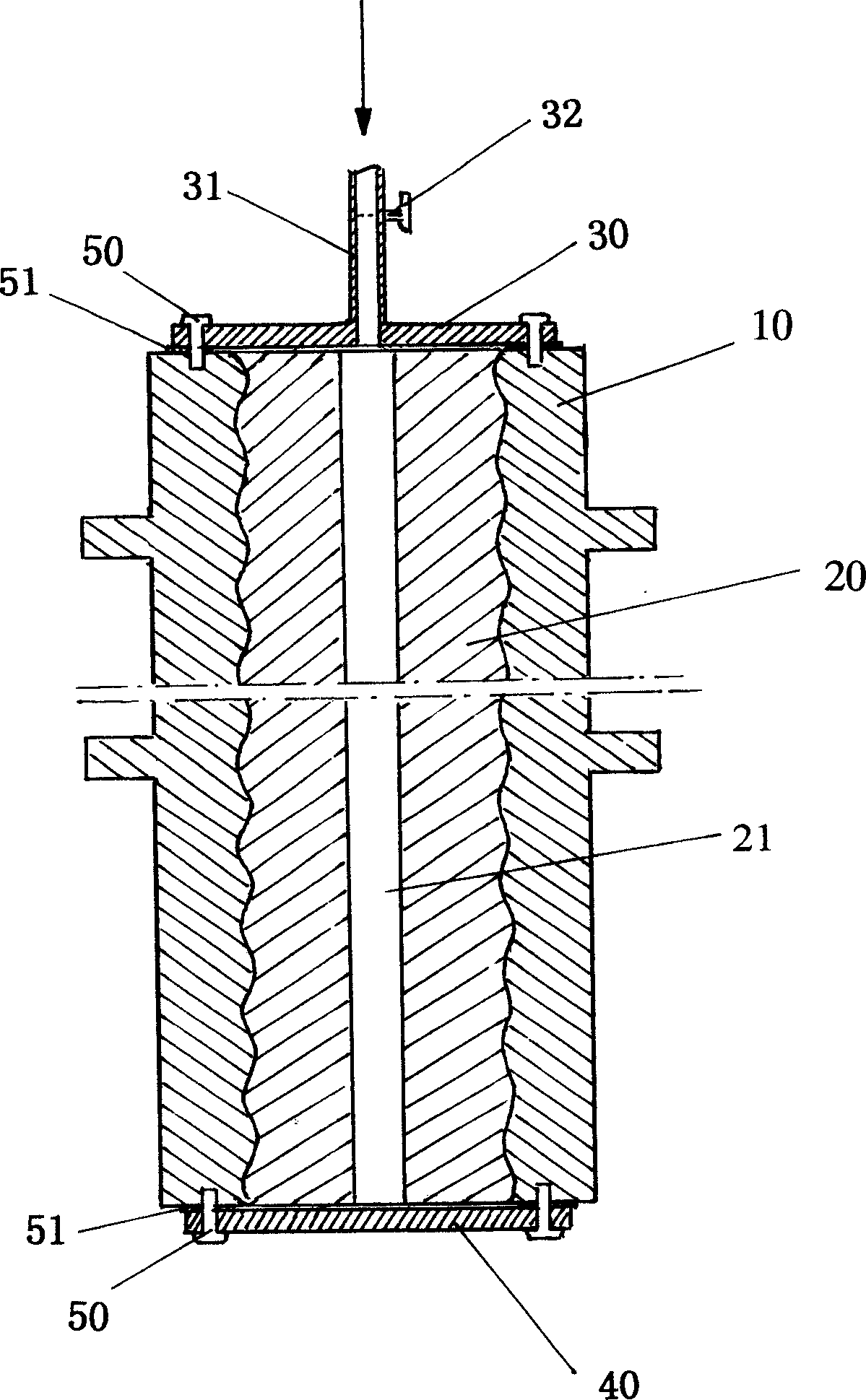
[0014] Such as figure 1 As shown, it is a schematic diagram of the structure of the pipe pile equipped with steam pipes according to the present invention. The steam pressurization manufacturing method of the pipe pile includes high-pressure steam treatment after the pipe pile 20 is centrifugally shaped, wherein, after the pipe pile 20 is centrifugally shaped, Install sealing steel plates 30, 40 at both ends of the two semicircular steel molds 10, and fix them with sealing washers 51 or fastening bolts 50, and the center of the sealing steel plate 30 at one end is equipped with a through hole 21 aligned with the center of the pipe pile 20 The steam pipe 31 is equipped with a steam valve 32 on the steam pipe 31. When the steam pipe 31 is connected with the high-pressure steam pipe (not shown in the figure), the steam valve 32 is opened and the high-pressure steam is connected to the pipe pile 20. Carry out heat treatment, after heat treatment, close steam vent valve 32, take of...


PUM


Abstract

The steam pressurizing pipe pile making process includes the high pressure steam treatment of pipe pile after centrifugal fixing. Two semi-circular steel cylinders and two sealing steel plates on two ends form the steam container with pipe pile inside it, and steam is led into pipe pile through the central hole on one steel plate via pipeline and valve to treat the pipe pile for 30-60 min. The present invention has greatly lowered power consumption, only one tenth of that of traditional technological process, raised pipe pile density, and raised pipe pile strength and quality.

Description

technical field [0001] The invention relates to a manufacturing method of building foundation pipe piles, in particular to a steam pressurized manufacturing method of pipe piles which can reduce costs, improve production efficiency and save a lot of energy. Background technique [0002] Energy saving is the direction that our society pursues and strives for, but there are still many traditional production processes because people have become commonplace and do not realize that certain technological reforms can improve production efficiency and save energy, but stick to backward production processes. , not only a waste of energy but also the cost of the product cannot be reduced, and the production efficiency cannot be improved. [0003] At present, the production of pipe piles is done after the concrete enters the mold and is centrifugally shaped. When the concrete is uniformly solidified on the outer wall of the steel mold, the workers lift the steel mold on the rail car by...

Claims


Application Information

Patent Timeline
IPC IPC(8): B28B11/00
Inventor 陈秋平
Owner 陈秋平
Features
  • Generate Ideas
  • Intellectual Property
  • Life Sciences
  • Materials
  • Tech Scout
  • Unparalleled Data Quality
  • Higher Quality Content
  • 60% Fewer Hallucinations
Learn More