Multifunctional machine clip turning tool

A multi-function machine and turning tool technology, which is applied to tools for lathes, turning equipment, accessories of tool holders, etc., can solve the problem that indexable inserts cannot be reground, and achieve the effect of simple and fast operation.

Inactive Publication Date: 2005-12-21
张邦南
View PDF0 Cites 4 Cited by
  • Summary
  • Abstract
  • Description
  • Claims
  • Application Information

AI Technical Summary

Problems solved by technology

The main structural feature of the indexable tool is the carbide insert with a triangular, square or other polygonal shape. The cutting edge on each side can be used for indexing on the tool body, but due to its clamping structure Due to the limitation of each cutting edge of the indexable insert, it is almost impossible to regrind after cutting wear, so the

Method used


Image

  • Multifunctional machine clip turning tool
  • Multifunctional machine clip turning tool
  • Multifunctional machine clip turning tool

Examples


Embodiment Construction

[0027] The present invention will be further described below in conjunction with the embodiment that accompanying drawing provides:

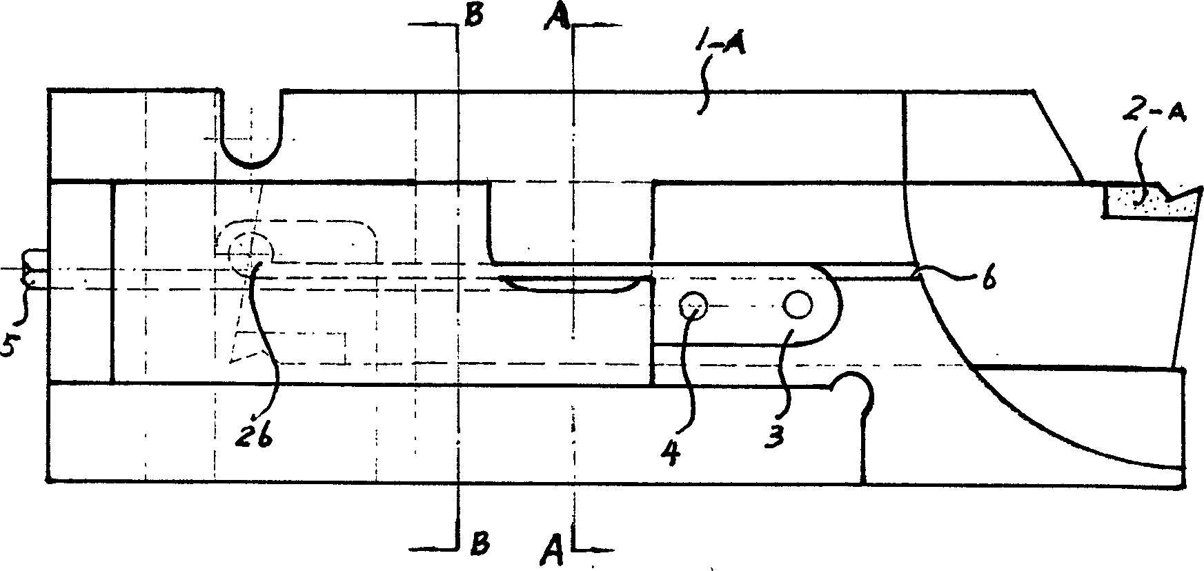
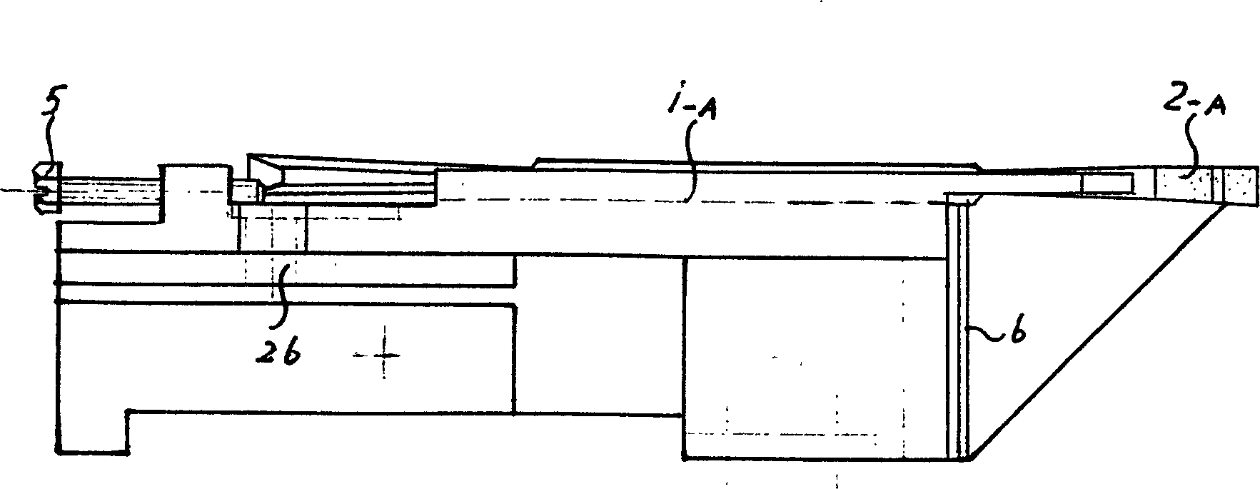
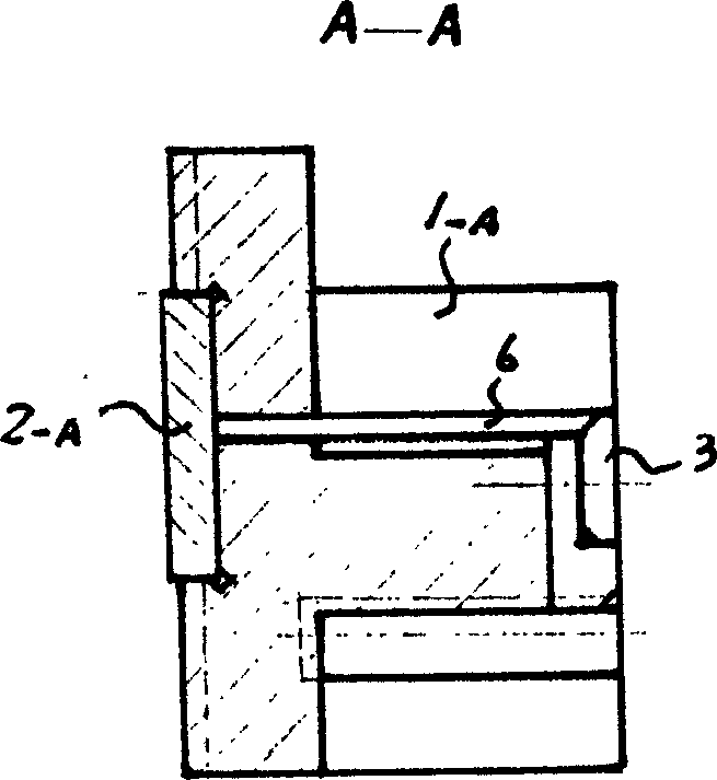
[0028] Figure 1 to Figure 4Among them, the cutter body 1-A, the blade 2-A, the balance weight 3, the balance weight fixing pin 4, and the adjustment screw 5 are composed of a positionable clamp cutter, which is a tool suitable for cutting workpieces. Blade 2-A is the elongated blade that all has blade at two ends, and its two ends blades are reversed namely blade use end upward spare end downward. 26 is an elastic hole. The upper end of the balance weight 3 is in line with the upper plane of the elastic slot 6 .

[0029] Figure 5 to Figure 8 Among them, there is a Shaped groove, the longitudinal edge of the groove extends to the cutter body afterbody, and its longitudinal groove forms two side planes 15,16 and a bottom surface 14; The groove divides the upper plane 13 of the cutter body 1-A into three sections (13- 1, 13-2, 13-3), the th...


PUM


Abstract

The present invention provides a kind of multifunctional reamer. On the left side of the reamer body next to end part there is an adjusting bolt which adjusts and locates the blade's longitudinal position. The reamer body's left side has an opened reamer trough that installs the blade. The other side of reamer trough has an elasticity trough that parallels with reamer trough and makes reamer trough and reamer body's head dredge and separate two parts which contains top and bottom, and the trough installs balance parts. After making the blade embed reamer body's trough and installing on the lathe knife rest, make the blade and the reamer body clamp and rivet by two bolts on the knife rest. The invention contains reamer cutting tools' and jointing cutting tools' good qualities. It is provided with many strong points such as handy operation, steady clamping, blade's perfect orientation, reamer body's many functions of a pole, cheap cutting tools' cost and so on.

Description

technical field [0001] The invention relates to a metal cutting tool, in particular a multi-functional cutting tool which can be used for cutting workpieces on a lathe or cutting end faces and outer circle parts on a lathe. Background technique [0002] 1. At present, although the mechanical clamping cutters that have been implemented in our country for many years have been accepted and applied on lathes to varying degrees, it is difficult to firmly clamp the JCQ-type blades manufactured and implemented in our country on the head of the cutter body. In practice, the uneven force on the blade often causes the blade to vibrate due to the fact that the blade is not clamped firmly, which eventually leads to accelerated fragmentation of the blade edge and damage to the blade's supporting plate. The world's first American Kennametal (Kennametal) cemented carbide machine clip indexable tool company and the self-cassette cutting knife structure, the cutting and cutting tools manufac...

Claims


Application Information

Patent Timeline
IPC IPC(8): B23B27/00
Inventor 张邦南
Owner 张邦南
Why Eureka
Try Eureka