Oscilloscope condition triggering method based on finit state machine

A finite state machine, oscilloscope technology, applied in instruments, digital variable/waveform display, measurement devices, etc., can solve problems such as powerlessness

Inactive Publication Date: 2005-12-21
SOUTHEAST UNIV
View PDF0 Cites 14 Cited by
  • Summary
  • Abstract
  • Description
  • Claims
  • Application Information

AI Technical Summary

Problems solved by technology

Most of the more complex trigger functions provided by high-end oscilloscopes are triggered for a specific situation, but for some special signals, especially waveforms with special shapes, they often seem powerless

Method used


Image

  • Oscilloscope condition triggering method based on finit state machine
  • Oscilloscope condition triggering method based on finit state machine
  • Oscilloscope condition triggering method based on finit state machine

Examples


Embodiment Construction

[0032] The implementation of the present invention can be divided into two parts: the finite state machine and the condition generator. Wherein, the finite state machine can be realized conveniently by logic devices, including programmable logic array (Field Programmable GateArray, FPGA) or application specific integrated circuit (ASIC). The condition generator can be implemented by an analog-to-digital converter (ADC)+logic device or a level comparator+logic device.

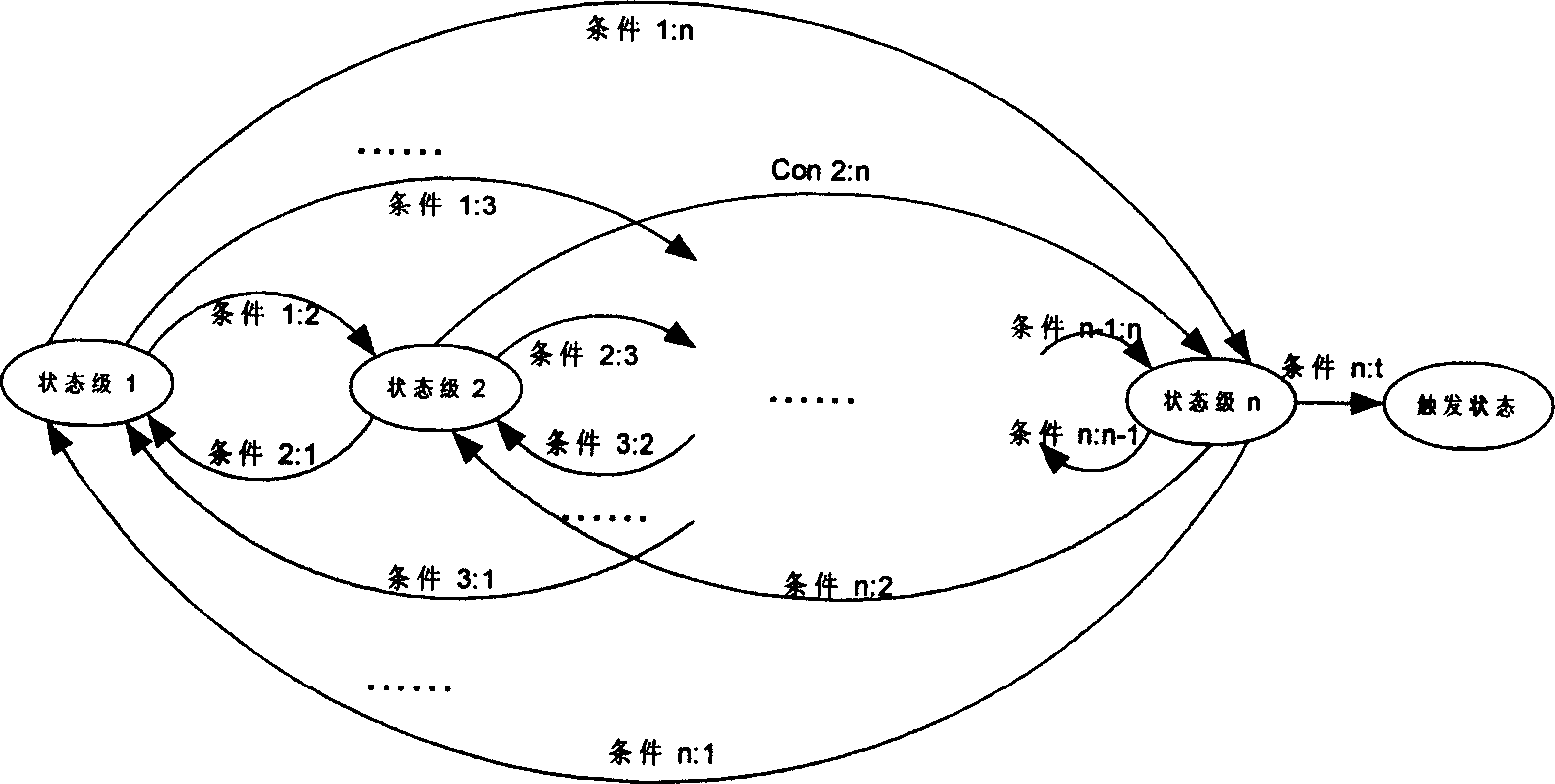
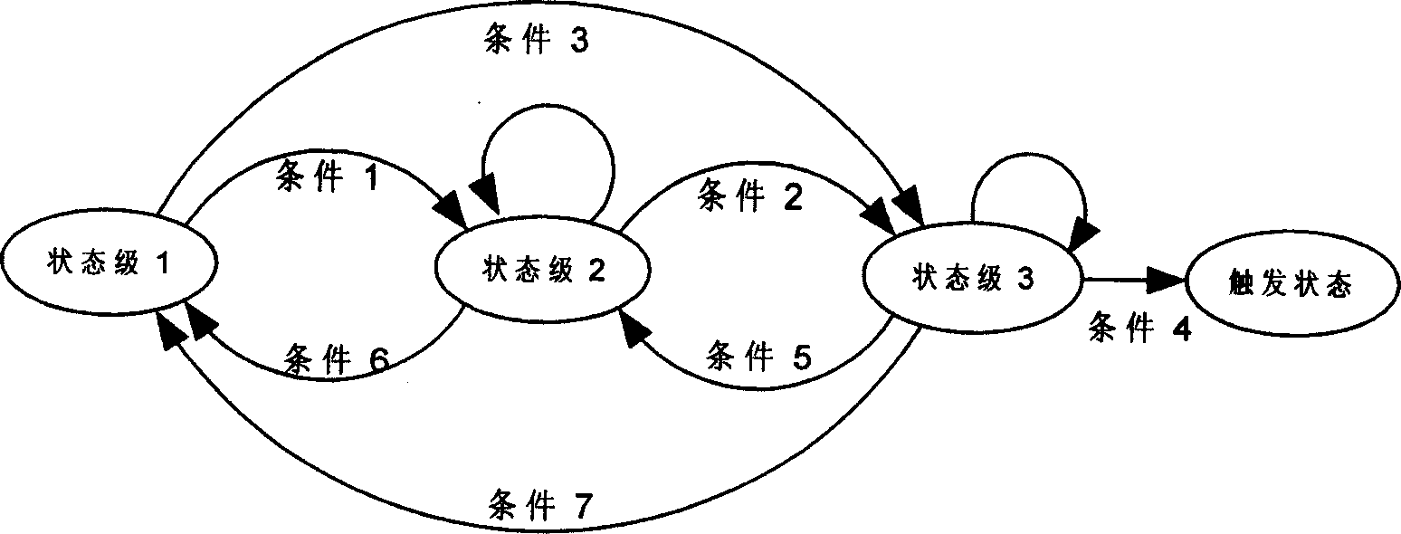
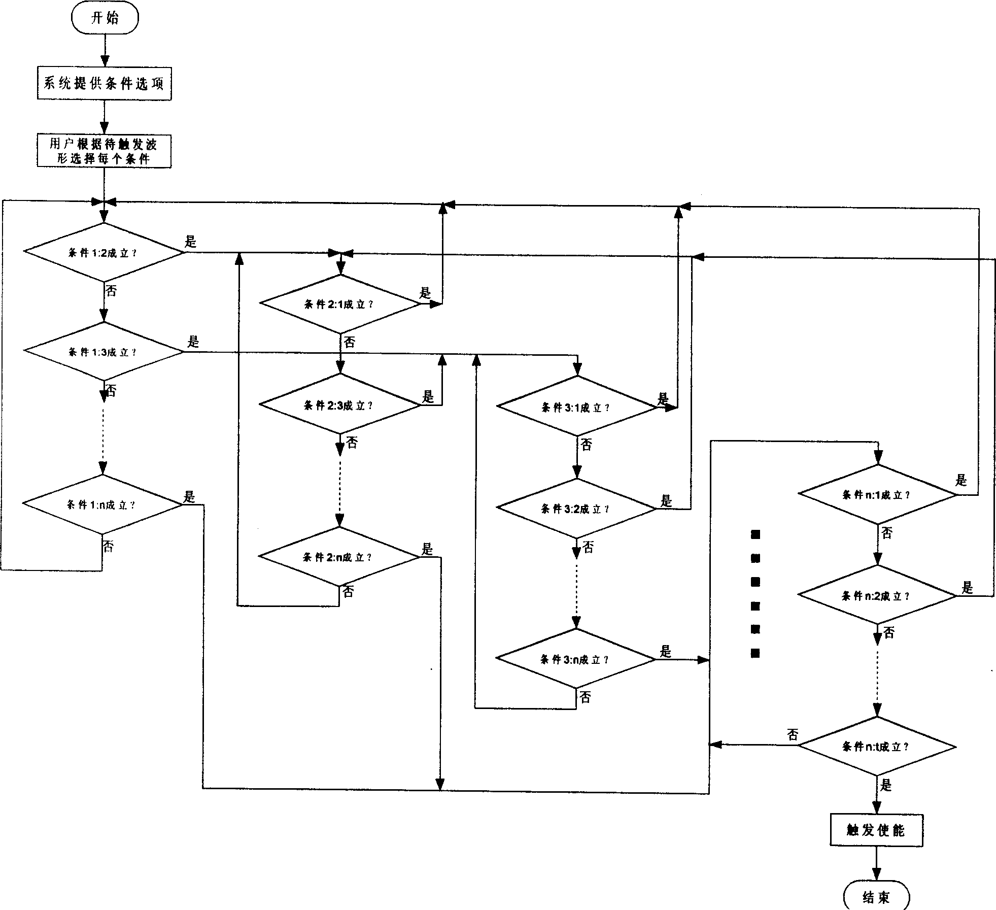
[0033] In the oscilloscope conditional trigger method based on the finite state machine of the present invention, the conditional trigger method is:

[0034] The user sets the number of stages of the state machine to n according to the complexity of the waveform, and n is an integer greater than or equal to 1; the system provides the user with four optional conditions, namely: ① automatic condition, ② edge condition, ③ timeout condition, ④ Prohibition conditions; Among them, the automatic condition means that t...


PUM


Abstract

A condition triggering method of oscilloscope based on finite state computer includes making state computer series be n which is integer being greater than or equal to one ; providing four selectable conditions by system to client as automatic condition referring that sub-condition is always being set up , edge condition referring that condition is being set up when specific edge polarity of specific electric level is satisfied , overtime condition referring that condition is being set up after specific delay time is satisfied and forbidden condition referring that this condition is never being set up.

Description

Technical field: [0001] The invention relates to a trigger method of an electronic measuring instrument, in particular to the technical field of an oscilloscope used for waveform display. Background technique: [0002] "Triggering" is an essential part of an oscilloscope. Without the function of triggering, it is difficult to stabilize the waveform display. For the capture and observation of some special waveforms, complex trigger mechanisms are unavoidable. A typical trigger machine has an input terminal and an output terminal, the input terminal is generally connected to the signal to be tested and the output terminal is connected to the waveform sampling controller. Its main working process is: the trigger machine continuously monitors the signal to be tested, and once the trigger condition is found to be met, the trigger machine outputs a trigger enabling signal. Therefore, the core of the trigger machine is the continuous monitoring of whether the signal to be tested...

Claims


Application Information

Patent Timeline
Patent Type & Authority Applications(China)
IPC IPC(8): G01R13/00
Inventor 戴戈
Owner SOUTHEAST UNIV
Why Eureka
Try Eureka